When we hear the words “pitot tube,” we tend to think more of airplanes than of air ducts, but [Franci Kopač]’s guide to pitot tubes for makers shows that they can be a remarkably versatile tool for measuring air speed, even in domestic settings.
A pitot tube is a tube which faces into an air flow, with one hole at the front of the tube, and one on the side. It’s then possible to determine the air speed by measuring the pressure difference between the side opening and the end facing into the wind. At speeds, temperatures, and altitudes that a hacker’s likely to encounter (i.e. not on an airplane), the pressure difference is pretty small, and it’s only since the advent of MEMS pressure sensors that pitot tubes became practical for amateurs.
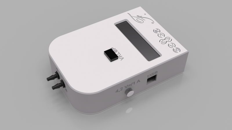
[Franci]’s design is based on a Sensiron SDP differential pressure sensor, a 3D-printed pitot tube structure, some tubing, and the microcontroller of your choice. It’s important to position the tube well, so that it doesn’t experience airflow disturbances from other structures and faces straight into the air flow. Besides good positioning, the airspeed calculation requires you to know the air temperature and absolute pressure.
[Franci] also describes a more exotic averaging pitot tube, a fairly simple variation which measures air speed in cavities more accurately. He notes that this provides a more inexpensive way of measuring air flow in ducts than air conditioning flow sensors, while being more resilient than propeller-based solutions – he himself used pitot tubes to balance air flow in his home’s ventilation. All of the necessary CAD files and Arduino code are available on his GitHub repository.
If you’re looking for a more conventional duct flow meter, we’ve covered one before. We’ve even seen a teardown of a pitot tube sensor system from a military drone.
Using Pitot Tubes For More Than Aircraft


This would probably also work with venturi tubes that might be easier to incorporate into certain designs due to them relying only on a constriction of the airflow (like narrowing the tube slightly) to create a measurable pressure difference that can be used to gauge the air (or fluid) flow.
Wikipedia has a nice video showing it: https://upload.wikimedia.org/wikipedia/commons/transcoded/5/58/Venturi_Tube_en.webm/Venturi_Tube_en.webm.480p.vp9.webm
Venturis restrict your airflow far more, but otherwise work similarly. So it depends on your air velocity — as soon as the air velocity is large enough, a Venturi wastes energy. But I’m sure there are applications where the air velocity is so small that it makes sense to create a restriction somewhere in the system.
Apart from that, I think the biggest inherent advantage of the Pitot tubes is you don’t need to calibrate them unless you want very high accuracy. Which is an insight I’ll add to the article, thank you :)
Seems like a great article. I’ll have to read it in full later. I wish the original article had a full drawing of where the sensors sit and all that. I guess it’s kind of intuitive from the math how all this is supposed to go but I really appreciate when people detail housings couplings etc. especially with a picture.
The final picture of the article shows the whole measuring setup for airflow measurement. I did not delve much in using the basic Pitot tube for direct air velocity measurements, like for a model airplane.
Of course, if you have questions, you can use the built-in comments on the blog or Medium, I’m happy to discuss the details or even update the article after we get somewhere with that.
Fords in the late 90s used this to measure flow in an emissions system, maybe EGR (exhaust gas recirculation), or AIR (air injection reaction).
Indeed, it was for EGR. Ford called it “Delta Pressure Feedback EGR,” or DPFE. They had a semi-flexible metal pipe around 18 mm diameter running from an exhaust manifold to the EGR valve. Two smaller steel tubes came off the main pipe, one larger than the other (about 4 and 6 mm maybe), from either side of an orifice inside the large main pipe. These were connected to the DPFE sensor via high-temperature silicone hoses; the sensor would output a voltage in proportion to the differential pressure. That pressure was indicative of the EGR flow to the intake manifold.
IME, it was more accurate than the older EGR Valve Position (EVP) sensors, which would only indicate pintle position. DPFE could give you an actual volume, IIRC, whereas EVP was a good guess at best, nevermind what happened when EGR passages would become clogged.
I actually went through the trouble of adding a DPFE system to my Bronco, after adding the necessary hardware, wiring, and reprogramming the EEC-IV PCM to use it. Actually, I added a device to the PCM that would allow me to modify the ROM contents, and then the PCM would happily read and use the data from it.
Why? Eh, I was an automotive nerd. It was something different and interesting to try, a long with the other fun and interesting modifications I was doing at the time.
we used pitot to measure water flow from fire hydrants
Can you elaborate, please, and give more details about the build?