An MRI scan is never a pleasant occasion – even if you aren’t worried about the outcome, lying still in a confined, noisy space for long periods of time is at best an irksome experience. For hearing protection and to ameliorate boredom or claustrophobia, the patient wears headphones. Since magnets and wires can’t be used inside an MRI machine, the headphones have to literally pipe the sound in through tubes, which gives them poor sound quality and reduces the amount of noise they can block. [SomethingAboutScience], however, thinks that photoacoustic speakers could improve on these, and built some to demonstrate.
Although the RTL-SDR is cheap, accessible, and capable enough for many projects, it does have some important limitations. In particular, its bandwidth is limited to about 3.2 MHz, and the price of SDRs tends to scale rapidly with bandwidth. [Anders Nielsen], however, is building a modular SDR with a target price of $50 USD, and has already reached a bandwidth of almost 20 MHz.
If this project looks familiar, it’s because we’ve covered an earlier iteration. At the time, [Anders] had built the PhaseLoom, which filters an incoming signal, mixes it down to baseband, and converts it to I/Q signals. The next stage is the PhaseLatch, a board housing a 20-MHz, 10-bit ADC, which samples the in-phase and quadrature signals and passes them on to a Cypress FX2LP microcontroller development board. [Anders] had previously connected the ADC to a 6502 microprocessor instead of the FX2LP, but this makes it a practical SDR. The FX2LP was a particularly good choice for this project because of its USB 2.0 interface, large buffers for streaming data, and parallel interface. It simply reads the data from the SDR and dumps it to the computer.
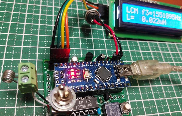
Although it dates back to the early days of the Marconi Company in the 1920s, the Franklin oscillator has remained a relatively obscure circuit, its memory mostly kept alive by ham radio operators who prize its high stability at higher frequencies. At the core of the circuit is an LC tank circuit, a fact which [nobcha] used to build quite a precise LC meter.
The meter is built around two parts: the Franklin oscillator, which resonates at a frequency defined by its inductance and capacitance, and an Arduino which counts the frequency of the signal. In operation, the Arduino measures the frequency of the original LC circuit, then measures again after another element (capacitor or inductor) has been added to the circuit. By measuring how much the resonant frequency changes, it’s possible to determine the value of the new element.
Before operation, the meter must be calibrated with a known reference capacitor to determine the values of the base LC circuit. In one iteration of the design, this was done automatically using a relay, while in a later version a manual switch connects the reference capacitor. Because the meter measures frequency differences and not absolute values, it minimizes parasitic effects. In testing, it was capable of measuring inductances as low as 0.1 µH.
Those who stay into the forbidden realm of font rendering quickly learn how convoluted and arcane it can be – LaTeX is a fully Turing-complete programming language, Unicode has over eighty invisible characters, and there are libraries that let you execute WebAssembly in a font. A great example of a font’s hidden capabilities is Z80 Sans, a font that disassembles Z80 opcodes to assembly mnemonics.
If one pastes Z80 opcodes into a word processor and changes their font to Z80 Sans, the codes are rendered as their assembly mnemonics. The font manages this by abusing the Glyph Substitution Table and Glyph Positioning Table, two components of the OpenType standard. Fonts define relations between characters (internal representations used by the computer, such as ASCII and Unicode) and glyphs (the graphics actually displayed).
In some cases, though, the way a character is displayed depends on where it appears in a word, or what appears around it (Arabic characters are a common example, but an example from English is the ligature “æ”). Z80 Sans defines all the possible glyphs for each nibble of the opcodes, then used a recursive descent parser to generate substitution rules which display the correct glyphs in context.
The rapidly-improving speed and versatility of digital computers has mostly driven analogue computers out of use in modern systems, as has the relative difficulty of programming an analogue computer. There is a kind of art, though, in weaving together a series of op-amps to perform mathematical calculations; between this, a historical interest in the machines, and their rarity value, it’s no wonder that new analogue computers are being designed even now, such as [Markus Bindhammer]’s system.
The computer is built around a combined circuit board and patch panel, based on the designs included in three papers in a online library of analogue computer references. The housing around the patch panel took design cues from the Polish AKAT-1 analogue computer, including the two dial voltage indicators and an oscilloscope display, in this case an inexpensive DSO-138. The patch panel uses banana connectors and the jumper wires use stackable connectors, so several wires can be connected to the same socket.
The computer itself has a summing amplifier circuit, a multiplier circuit, an integrator, and square, triangle, and sine wave generators. This simple set of tools is enough to simulate both simple and complex math; for example, [Markus] squared five volts with the multiplier, resulting in 2.5 volts (the multiplier divides the result by ten). A more advanced example is a leaky-integrator model of a neuron, which simulates a differential equation.
There’s a well-known movie trope in which a hacker takes control of the traffic lights in a city, causing general mayhem or creating a clear getaway path. Unlike many Hollywood representations of hacking, this is actually possible in principle; many cities install Emergency Vehicle Preemption (EVP) systems in their traffic signals to turn them green when an emergency vehicle is approaching. To see what it would actually take to control one of these, [xssfox] reverse-engineered a Strobecom II EVP system.
Most EVP systems, particularly older ones, use a strobing infrared light to alert a traffic signal to an approaching emergency vehicle. To avoid misuse, vehicles often encode a vehicle ID in the infrared signal. There have been some claims that a Flipper Zero can trigger these systems, but none that were well-verified, and probably with good reason; anyone actually trying this against a live system is courting serious legal trouble. To see whether this was actually possible [xssfox] obtained real hardware and tried to reverse-engineer the infrared protocol.
There are two main manufacturers for optical EVP systems: GTT Opticom and Tomar Strobecom. [xssfox] managed to buy a Tomar power supply which handled the processing for signal transmission, and which worked with Opticom systems. Looking at the output of this revealed that it encoded data by skipping pulses, which should be simple enough for Flipper Zero to replicate.
To reverse-engineer the Strobecom protocol, [xssfox] managed to buy a Strobecom optical signal processor, which would normally detect an emergency signal. This worked by modulating the length of infrared pulses. After some brute-forcing, a transmitter using an Arduino Nano and an infrared LED managed to activate the preemption signal, and even to transmit a vehicle ID. It seems that Strobecom systems, at least, are fairly demanding in terms of the signals they accept; signals had to be precisely timed, and in at least some systems, a valid vehicle ID would be needed to change the light.
[Diffraction Limited] has been working on a largely 3D-printed micropositioner for some time now, and previously reached a resolution of about 50 nanometers. There was still room for improvement, though, and his latest iteration improves the linkage arms by embossing tiny ball joints into them.
The micro-manipulator, which we’ve covered before, uses three sets of parallel rod linkages to move a platform. Each end of each rod rotates on a ball joint. In the previous iteration, the parallel rods were made out of hollow brass tubing with internal chamfers on the ends. The small area of contact between the ball and socket created unnecessary friction, and being hollow made the rods less stiff. [Diffraction Limited] wanted to create spherical ball joints, which could retain more lubricant and distribute force more evenly.
The first step was to cut six lengths of solid two-millimeter brass rod and sand them to equal lengths, then chamfer them with a 3D-printed jig and a utility knife blade. Next, they made two centering sleeves to hold small ball bearings at the ends of the rod being worked on, while an anti-buckling sleeve surrounded the rest of the rod. The whole assembly went between the jaws of a pair of digital calipers, which were zeroed. When one of the jaws was tapped with a hammer, the ball bearings pressed into the ends of the brass rod, creating divots. Since the calipers measured the amount of indentation created, they was able to emboss all six rods equally. The mechanism is designed not to transfer force into the calipers, but he still recommends using a dedicated pair.
In testing, the new ball joints had about a tenth the friction of the old joints. They also switched out the original 3D-printed ball mount for one made out of a circuit board, which was more rigid and precisely manufactured. In the final part of the video, he created an admittedly unnecessary, but useful and fun machine to automatically emboss ball joints with a linear rail, stepper motor, and position sensor.
On such a small scale, a physical ball joint is clearly simpler, but on larger scales it’s also possible to make flexures that mimic a ball joint’s behavior.