The ARRL used to have a requirement that any antenna advertised in their publications had to have real-world measurements accompanying it, to back up any claims of extravagant performance. I’m told that nowadays they will accept computer simulations instead, but it remains true that knowing what your antenna does rather than just thinking you know what it does gives you an advantage. I was reminded of this by a recent write-up in which the performance of a mylar sheet as a ground plane was tested at full power with a field strength meter, because about a decade ago I set out to characterise an antenna using real-world measurements and readily available equipment. I was in a sense field testing it, so of course the first step of the process was to find a field. A real one, with cows.
Walking Round And Round A Field In The Name Of Science

The process I was intending to follow was simple enough. Set up the antenna in the middle of the field, have it transmit some RF, and measure the signal strength at points along a series of radial lines away from it I’d end up with a spreadsheet, from which I could make a radial plot that would I hoped, give me a diagram showing its performance. It’s a rough and ready methodology, but given a field and a sunny afternoon, not one that should be too difficult.
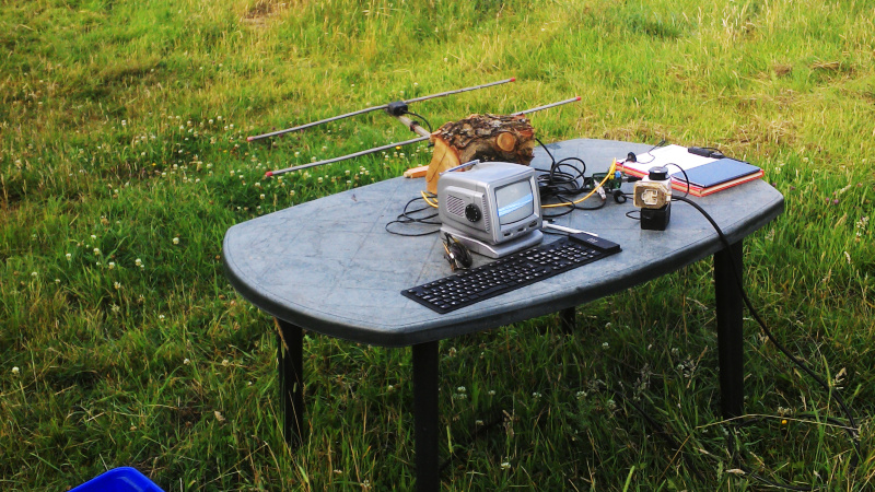
I was more interested in the process than the antenna, so I picked up my trusty HB9CV two-element 144MHz antenna that I’ve stood and pointed at the ISS many times to catch SSTV transmissions. It’s made from two phased half-wave radiators, but it can be seen as something similar to a two-element Yagi array. I ran a long mains lead oput to a plastic garden table with the HB9CV attached, and set up a Raspberry Pi whose clock would produce the RF.
My receiver would be an Android tablet with an RTL-SDR receiver. That’s pretty sensitive for this purpose, so my transmitter would have to be extremely low powered. Ideally I would want no significant RF to make it beyond the boundary of the field, so I gave the Pi a resistive attenuator network designed to give an output of around 0.03 mW, or 30 μW. A quick bit of code to send my callsign as CW periodically to satisfy my licence conditions, and I was off with the tablet and a pen and paper. Walking round the field in a polar grid wasn’t as easy as it might seem, but I had a very long tape measure to help me.
A Lot Of Work To Tell Me What I Already Knew

I ended up with a page of figures, and then a spreadsheet which I’m amused to still find in the depths of my project folder. It contains a table of angles of incidence to the antenna versus metres from the antenna, and the data points are the figure in (uncalibrated) mV that the SDR gave me for the carrier at that point. The resulting polar plot shows the performace of the antenna at each angle, and unsurprisingly I proved to myself that a HB9CV is indeed a directional antenna.
My experiment was in itself not of much use other than to prove to myself I could characterise an antenna with extremely basic equipment. But then again it’s possible that in times past this might have been a much more difficult task, so knowing I can do it at all is an interesting conclusion.


These days, a better way to characterize an antenna is to put an oscillator on a drone and record the result at the antenna with a receiver. My drone tells me pretty accurately where it is for height and X-Y position, and my HF receiver can show me the signal in microvolts, so I can plot a full 3 dimensional plot. If you use a noise generator on the drone and an SDR with a spectrum display for the receiver you can get the frequency response as well.
The trick is to keep the short transmit antenna on the drone properly oriented for direction and polarization, but for horizontal polarization that’s pretty easy … orient the antenna crossways on the drone and keep the drone always pointed toward the test antenna. Not as straightforward for vertical polarization since the drone doesn’t like to tilt.
It would be nice where I test VHF antennas, as I use a drop-off hillside, with the other end some km away. The DUT still needs to rotate as the clear drop off is on one side only. This only makes it easier as the drone just needs to stay on one spot, or go up and down a vertical column.
The real power of this idea would be for HF antennas, where the 3D pattern is important, you can’t rotate it or walk around it, and you can’t model it accurately if the actual ground is not flat, and you don’t know the resistivity.
I actually used my drone to measure the elevation pattern of a 5 element HF wire log periodic antenna that I built for solar noise reception (check out the Radio Jove project). It was good from about 13 MHz to 30 MHz and I tilted it upward at an angle of roughly 70 degrees. It was fixed (not rotatable) so I only had to do it from one direction. I cobbled together a 9 volt crystal oscillator for 20 MHz and mounted it on the drone with a short dipole taped across the front legs under the drone. I pre-calculated the horizontal distance and vertical height in ten degree increments to keep the drone always 200 feet away from the antenna … i.e. X=200/Y=0, X=197/Y=35, X=188/Y=68, X=173/Y=100, etc and then just flew the drone to those positions while my wife recorded the signal strengths from the receiver. I compared the results to the predicted elevation pattern I got from EZNEC and it was very close.
This guy is really having a field day.
Field plot looks symmetrical, and that gives some confidence. Maybe groundwater level, soil composition or the fence far away distorts the measurements. (cloud formations?) I would start by putting the receiver far away on a long cable, then do the measurements by rotating the antenna itself, pull in a few meters of cord to get the receiver closer and repeat a few times. By rotating the antenna instead of the receiver a lot of the environmental variables are constant, and thus cancel themselves out. But of course the physical exercise would be lacking with that method.
With the extra left over time, you can repeat the whole thing in another direction to double check.
Good radio hobbyists, like good farmers, are usually out standing in their field.
Have any HaD editors made contact with each other over any of the amateur bands? Dan Maloney did the 50 dollar ham series I think, I assume you’re licensed as well there Jenny
Oddly not, afaik. I do have a G7 call, but I don’t use it for operating, instead I like building radios.
Idea: Hackaday beacon set up temporarily for WSPR. Swap out the Maidenhead location for ‘HAD’
The place where the test is done is very relevant. Relief, vegetation, soil type, minerals in the area, humidity, earth magnetic field, etc.