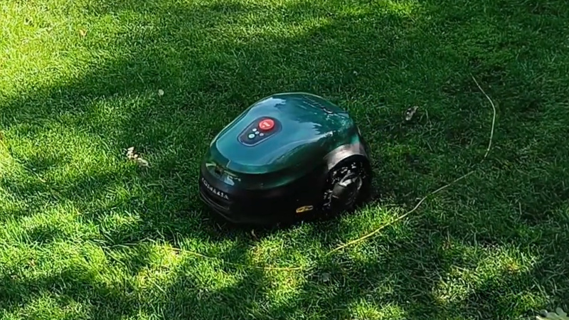
There are a variety of robot mower systems on the market employing different navigation methods, and [Eelco] has the story of how one of these was reverse engineered. Second hand Roomba lawnmowers kept appearing for very low prices without the electronics driving the buried-wire fence that keeps them from going astray. The story of their reverse engineering provides us with a handy insight into their operation.
The wire fence is a loop of wire in the ground, so it was modeled using a few-ohm resistor and the waveform across it from a working driver captured with an oscilloscope. The resulting 3 kHz waveform surprisingly to us at least doesn’t appear to encode any information, so it could be replicated easily enough with an ESP32 microcontroller. An LM386 audio amplifier drives the loop, and with a bit of amplitude adjustment the mower is quite happy in its fake fence.
Robot mower hacking has become quite the thing around here.


For an in-depth explanation of an accurate perimeter wire system, and how they can do neat stuff like detect the loop’s signal even when it is under the noise floor… or detect when it is inside or outside the loop… check out this video (German with English captions and link in comments)
https://www.youtube.com/watch?v=NIer_kITelc
“Second hand Roomba lawnmowers kept appearing for very low prices without the electronics driving the buried-wire fence”
Sounds like stolen goods to me :)
Or just “we’ve replaced it and don’t want to dig up the damn wire”.
The base station for one mower is rarely compatible with another mower so you’d replace that at the same time but re-use the buried wire.
I once blew up a base station by reversing polarity while swapping the mains power supply for a solar panel and battery. In my defence the wires were red and blue, why was blue positive? I called the manufacturer and said I wanted to buy a replacement base station but they wouldn’t sell me one even with proof of purchase “to reduce theft”. The only way to get a new one was to buy one bundled with a mower.
So be very wary of a mower without a base station both because it might be stolen and you might not be able to use it.
Very disappointing, I thought this was going to be a GPS mod or something cool, but instead it’s just enabling the crime of handling stolen goods.
What’s to say a GPS hack couldn’t be used the same way?
Wow an ESP32 to produce a 3KHz waveform. Whatever happened to a 555? Or a transistor astable multivibrator?
Yeah, tell us you didn’t look at the article without telling us you didn’t look at the article.
Here’s a hint – they said “waveform”, not “sine wave”.
The article appears to show a distorted (looks like it’s generated by an H bridge and smoothed with passives) 3kHz sawtooth with no information (in the information theory sense) embedded in it, so most likely could be replaced with a simple signal generator. And that kind of makes sense, a sawtooth has phase information that could help reduce interference from nearby loops as long as they are all connected in the same direction. That’s just from their description, maybe the code shows some modulation that isn’t mentioned in the description. Or did you spot something I missed @pelrun?
I don’t think it’s that special.
Yup.
What happened to the 555 was that microcontrollers got absurdly cheap.
Roomba? The article talks about Robomow units. Roomba doesn’t do robot mowers.
I picked up a Husqvarna version last fall and it ran beautifully through the spring until my neighbor shorted out the fence and destroyed it in a couple places by putting up his own fence to keep the deer away from his tomatoes. I’ve tried getting it working a few times over the summer, but I haven’t had the time to dig up the entire fence that I took about two weeks to get right the first time. And I really wish I could eliminate the fence completely and just use GPS or something.
One of these weekends I got to borrow a signal generator from an electrician friend and see if I can find the break. I have an unusual shaped yard and there’s lots of turns so I’m hoping that will help me from having to dig up everything again.
Why not build a receiver circuit and detect the signal?
Half of the circuit should be detectable up until approximately the break point.
An old AM radio could potentially work too, although that’s easier to test on a fully working setup first.
You might want to look at fox and hound signal injector/detector and see how they work perfectly well for tracing open circuit wiring
Would this Vevor unit from Home Depot do the trick?
https://tinyurl.com/3jzsysvs
Looking at the waveform that the author super-faithfully reproduced with his wave table and ESP32 DAC, my intuition tells me that the original hardware is even simpler, maybe just a pulse generator, with the sine wave “on the wire”derived not from an analog source, but a cheap low-pass filter. The waveform asymmetry is intriguing though.
This is all fun n stuff, but has anyone turned one of these into a BigTrak?