When you are capturing audio from a speaker, you are rarely capturing the actual direct output of such a system. There are reflections and artifacts caused by anything and everything in the environment that make it to whatever detector you might be using. With the modern computation age, you would think there would be a way to compensate for such artifacts, and this is what [d.fapinov] set out to do.
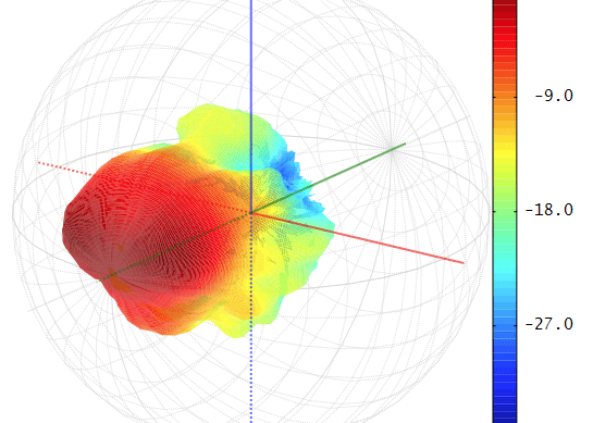
[d.fapinov] has put together a code base for simulating and reversing environmental audio artifacts made to rival systems, entirely orders of magnitude higher in cost. The system relies on similar principles used in radio wave antenna transmission to calculate the audio output map, called spherical harmonic expansion. Once this map is calculated and separated from outside influence, you can truly measure the output of an audio device.
The only problem is that the project needs to be tested in the real world. [d.fapinov] has gotten this far but is unable to continue with the project. A way to measure audio from precise locations around the output is required, as well as the appropriate control for such a device.
Audio enthusiasts go deep into this tech, and if you want to become one of them, check out this article on audio compression and distortion.


This is obviously incredible, but I’m not much knowledgeable about sound recording. What are the usual reasons to capture sound from a speaker rather than plug in directly into the stereo channel of the amp the speakers are playing from ?
It’s precisely because the OP wants to know what the speakers sound like, free of interference from the room that they’re situated in.
Indeed, I commented a bit too fast… Thanks !!
Measure the speakers in an acoustic anechoic chamber. That room is designed to have no interaction with the speaker.
“called spherical harmonic expansion” or rather spherical harmonics expansion, because ist an expansion in spherical harmonics, a function set?
Record the characteristics in more than one environment then find the difference.
You can’t find enough environments with enough variety to solve the problem like that. It would just be a few different variations on “broken.”
Ideally you’d do this testing in an anechoic chamber where the “environment” essentially doesn’t exist. But those are expensive.
interesting. its the exact opposite of what a impulse response is trying to achieve: adding artificial reverb to a dry signal. maybe that route is also possible.
I’m sure there are probably ways to try to reverse back to an estimated impulse response (actually, there are ABSOLUTELY methods to do so). Though, which I also immediately thought of impulse responses, this seems to include directionality. In other words, building a directional map rather than just sum all the signals coming from all directions together into single signal.
Wow! Just what I need. I’ve been a Hammond/Leslie tech for many years and have been working on a way to accurately document the sound characteristics of Leslie speakers on location – mainly in church auditoriums. Occasionally, I’ll run across one with a “sweet” sound but room acoustics just don’t allow for accurate measurements. I have some Leslies that I’ve considered testing in an open field so I posted a question to AI about what to expect. The response I got was that there are known techniques for obtaining relatively accurate measurements (on a par with an anechoic chamber), but were limited to around 500Hz and above. The Hammond organ goes down to about 30Hz so that’s as far as I got. But, I’m ALL IN for working with others on putting a Leslie (or any other speaker) on a carousel and/or attaching a calibrated mic to a robotic arm if the techniques discussed here will give reliable results.
For an open field the main problem is refection off the ground, which has 2 effects: both the direct speaker output and the reflected output are detected by the microphone, and the ground raises the acoustic impedance seen by the speaker (raising the low frequency response.)
Both problems can be addressed by raising the speaker off the ground. Most of the acoustic impedance changes are minimized by getting the woofer at least 1/6 wavelength high; that’s 6.1 feet
or 1.86 m at 30 Hz. Minimizing the effect of the reflected wave at the microphone requires making the direct path to the microphone much shorter than the reflected path. There are difficulties with microphone placement because even the direct response varies wildly with position with respect to the speaker. Get a ladder and experiment with microphone positions.
Alternately, don’t bother raising the speaker off the ground. If your application has the speaker on the floor, then the ground will affect performance similarly to a floor, especially at low frequencies.
It’s not invalid to just get a half-space response. Unless the speaker is vented in back, just lay the speaker flat on the ground and make measurements with the microphone 6 feet or so above the speaker. This will boost low frequency response by as much as 3 dB compared to a free space measurement.
It’s possible that what you hear as “sweet” sound is due more to room acoustics than speaker response, so keep that in mind.
Pretty sure you can find open air test results for standard Leslie speakers.
Of course, I doubt one exists in unmodified/repaired condition.
Those are easy compared to room acoustics.
Most people say F-it and just go with built in test instruments.
Sit in various places.
Go with gut.
Even the best designed, purpose built symphony halls are ‘adjusted’ by ‘golden ear’ listeners directing wall hanging adjustments prior to opening and after changes.
They fill the room with volunteers and symphony, the meatbags absorb much more sound then the seats.
Dead rooms (most equal to open fields) are terrible sounding.
Musicians aren’t interested in flat frequency response, they want amps that ‘sound good’.
Organists are no different.
Rooms same as amps, only thing that matters is ‘it sounds good’.
‘Pink noise/microphone adjustment built into modern amps is a good place to start the room tune.
This is a fancy version of that.
Be the guy who suggests:
‘A tapestry on that wall might make the whole room sound much better. Lets test with a hanging white blanket next Sunday.’
‘Heavy curtains are making room sound like inside of padded cell. Let’s test hang glass fronted pictures on walls as reflectors.’
‘Let’s try moving the PA speakers to about 1/5 and 4/5 of the room’s width, 1/3 or the way up.’
as case may be.
Of course it’s a church, so respect the choir directors authoriti!
That’s who you want to diplomatically direct the suggestions too.
Find something other than ‘padded cell’ to represent a dead room.
You don’t really know what the rooms sound like full of god botherers.
Don’t assume.
I needed to measure speaker performance without reflections some time ago. I didn’t have access to the fancy analysis tools (heck they didn’t exist). Nor did I have an anechoic chamber handy.
I did have a nearby open field with clear sky above though. A perfect empty hemisphere. No echo, no reverberation. Worked great.
So this solution relies on a static map of the environment around the speaker for calibration and lots of computation to obtain a signal; what’s the utility in that? Except in a few very narrow cases, or in controlled environments, the world is a very dynamic place; always changing, even in small ways that would invalidate the mapping, and all that computation would no longer output a signal with fidelity.
What advantage does this method of audio input have over a more conventional sensor that does not require this computational overhead and awareness of the environment?
This reminds me of those old plate cameras that required long exposures to obtain a picture. “Stand still while I take your picture!” They might have been able to obtain an image, but couldn’t really capture, with fidelity, the likeness of the dynamic life in front of them. Not many landscapes or pictures of animals back then.
I Think the angle you might require is to investigate what is available in the MEMS arena for microphone elements, I have been thinking about building a tiny regular dodecahedron with a MEMS element on the centre of each face. Think: how they do timings for a binaural head dummy, but pure hemispherical overlapping coverage from the total of the faces…. It does cost in preamp gear, but it gives you a very accurate level/angle/azimuth based way to compute all of these mostly hidden features of how sound works on a human ear set.
What about laser bounce off of speaker cone covered in a gold foil? Or convolution?
In typical hackaday commenter fashion, I will -now- avail myself of the actual article!
I’m pretty sure I saw this measurement demonstrated whilst measuring the response of a 3D printed speaker enclosure in an ordinary room. The trick is to use windowing on the time domain data to exclude multi-path. The only disadvantage is that you don’t get a very good low frequency response. In the RF domain the antenna or Radiohead unit is mounted on a rotator fixed to a pole in an anechoic chamber. The measurement antenna is in a fixed position and the DUT is rotated to derive the radiation pattern. I would have thought this technique would also work for an audio set up, and would be easier than moving the measurement microphone.
Since others have suggested far field measurements in an open field, I’ll suggested time gated near field measurements. Professionals use a Klippel NFS system that I assume is major $$s. People over at the Audio Science Review forum have “replicated” that system using REW and other less $ instrumentation. My concern would be that when extrapolating the FF power spectrum from the NF data and comparing it to the simulated FF, which do you have more confidence in when they invariably differ? Perhaps just a few FF measurements in an open field might suffice ?
I came here to say this!
Sounds like they’re trying to reinvent the wheel
Back in the early ‘80s, I worked at Altec Lansing (when they were one of the few major loudspeaker manufacturers in the industrial/professional arena, not the wimpy plastic desk speaker company they became) developing new production test methodologies. My co-worker and I implemented systems using an Apple II+, some hardware made by a company called IQS, and some software we wrote to perform averaged impulse testing on both the acoustic response and the impedance of compression drivers and complete systems on the production floor. The compression drivers were mounted on a plane-wave tube, and we built a small isolation room for the systems. The results correlated well with the responses we measured in our anechoic chamber.