Radio experimenters often need a variable capacitor to tune their circuits, as the saying goes, for maximum smoke. In decades past these were readily available from almost any scrap radio, but the varicap diode and then the PLL have removed the need for them in consumer electronics. There have been various attempts at building variable capacitors, and here’s [radiofun232] with a novel approach.
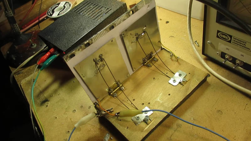
A traditional tuning capacitor has a set of meshed semicircular plates that have more of their surface facing each other depending on how far their shaft is turned. The capacitor presented in the first video below has two plates joined by a hinge in a similar manner to the covers of a book. It’s made of tinplate, and the plates can be opened or closed by means of a screw.
The result is a capacitor with a range from 50 to 150 picofarads, and in the second video we can see it used with a simple transistor oscillator to make a variable frequency oscillator. This can form the basis of a simple direct conversion receiver.
We like this device, it’s simple and a bit rough and ready, but it’s a very effective. If you’d like to see another unusual take on a variable capacitor, take a look at this one using drinks cans.


Mann-Russell Electronics of Tacoma, WA made RF gluing machines for wood glues. Hand held and also very large for things like their continuous beam presses that made architectural wood beams. The wood was fed continuously, squeezed and passed between long aluminum plates. It took about 4 minutes to pass through and the glue was cured. There were small units of a few kw and large ones of a Mw. The company made their own RF transformers and had a side-market for commercial radio stations. The gluing machines ran at around 1MHz and had a problem with variations due to water content of wood, etc. The capacitors in the transmitter were large aluminum plates at least 60x60cm. The problem was solved with a hinge on one side and a stepper motor driving a rod at the other side to vary the gap, around 1978, with a digital frequency counter circuit.
Mr. Mann, a shop teacher, and Mr. Russell, the business man (and uncle of the Russell 2000), were convinced they were making microwaves. I’m sure it was a Maxwell Induction Current.
Closer to microwave operating principle than induction: It’s dielectric loss tangent in action.
I don’t recall the E&M derivation but induction as in the water molecules are induced to move back and forth, not rotate like a microwave. Maybe it was “Maxwell Displacement Current”. At the time my E&M course was only 2 or 3 years previous.
I still need to make a variable capacitor for my magnetic loop antenna; the capacitor I have for it works, but it’s a tuning capacitor and takes too many turns to adjust when I want to change the band.
Some receive loops use servomotors & gears to allow fine tuning.
On transmit, most loop owners focus on the high voltages those capacitors need to withstand. Even if your capacitor can handle it, remote tuning keeps your fingers away from the Ouchie stuff.
You also don’t want to be sitting within arms reach of the tuning capacitor on a transmitting loop antenna if you’re running more than QRP. Remote tuning will save a lot of going back and forth.
Have you seen the tuning capacitor made of circuit board scraps and pot scrubbers, courtesy of Harry SM0VPO?
https://swling.com/blog/tag/homebrew-tuning-capacitor/
DC bias on dielectric causes change in dielectric thickness…higher voltage makes for thicker dielectric, lower capacitance.
What dielectric behaves in this unusual fashion?
A reversed bias PN Junction in a varicap diode.
True, the depletion zone changes apparent thickness, but I’m guessing that’s not what Gallacci had in mind.
I can’t see into that mind, but maybe conflating electrolytic caps oxide layer with cheap ceramic cap performance?
Sounds like a Y5V ceramic. Take a look at Barium Titanate as a great example of unusualness.
That cheap ceramic changes dielectric constant, true, but doesn’t change thickness…
Isn’t it used for SONAR transducers?
Oh come on … there is no way this is “a novel approach”. This is almost exactly how variable capacitors were first made for radios over 100 years ago. I’ve owned antique radios that had this kind of tuning capacitor.
It’s novel to radio constructors here in 2025.
http://c8.alamy.com/comp/ED4AW0/this-variable-capacitor-once-used-at-the-lahti-broadcasting-station-ED4AW0.jpg
— BUT —
Young(er) readers will likely have little ‘old’ knowledge of such devices, so there is value in posting articles that involve novel and non-traditional approaches to the physics surrounding radio engineering.
Hmmm. A working miniature of some Krell technology?
Anyone come up with an OpenSCAD script to create various sized rotor/stator plates for a DIY air variable capacitor with both sides of each plate being covered with copper or aluminum tape and threaded rod used for assembly?
Forgot to mention that the rotors/stators would be 3D printed.
Ol’ folk may remember the term “gimmick” for a capacitor made by twisting insulated wires. In reality, the term can be extended to represent any DIY capacitor as seen in my hackster.io project for creating a 2-component 16MHz Arduino barebone.
http://hackaday.io/project/204063-gimmick-on-barebones-arduino-16mhz
The phrase is “Tune for least smoke” for adjusting a transmitter tank circuit to resonance.