There’s many different ways of measuring current. If it’s DC, the easiest way is to use a shunt resistor and measure the voltage across it, and for AC you could use a current transformer. But the advent of the Hall-effect sensor has provided us a much better way of measuring currents. Hall sensors offers several advantages over shunts and CT’s – accuracy, linearity, low temperature drift, wider frequency bandwidth, and low insertion loss (burden) being some of them. On the flip side, they usually require a (dual) power supply, an amplification circuit, and the ability to be “zero adjusted” to null output voltage offsets.
[Daniel Mendes] needed to measure some fairly high currents, and borrowed a clip-on style AC-DC current probe to do some initial measurements for his project. Such clip on current probes are usually lower in accuracy and require output DC offset adjustments. To overcome these limitations, he then built himself an invasive hall sensor current probe to obtain better measurement accuracy (Google Translated from Portugese). His device can measure current up to 50 A with a bandwidth stretching from DC to 200 kHz. The heart of his probe is the LAH-50P hall effect current transducer from LEM – which specialises in just such devices. The 25 mV/A signal from the transducer is buffered by an OPA188 op-amp which provides a low output impedance to allow interfacing it with an oscilloscope. The op-amp also adds a x2 gain to provide an output of 50 mV/A. The other critical part of the circuit are the high tolerance shunt resistors connected across the output of the LAH-50P transducer.
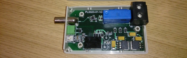
The rest of his design is what appears to be a pretty convoluted power supply section. [Daniel] wanted to power his current probe with a 5V input derived from the USB socket on his oscilloscope. This required the use of a 5 V to 24 V boost switching regulator – with two modules being used in parallel to provide the desired output power. A pair of linear regulators then drop down this voltage to +15 / -15 V required for the trasducer and op-amp. His blog post does not have the board layout, but the pictures of the PCB should be enough for someone wanting to build their own version of this current sensor.


