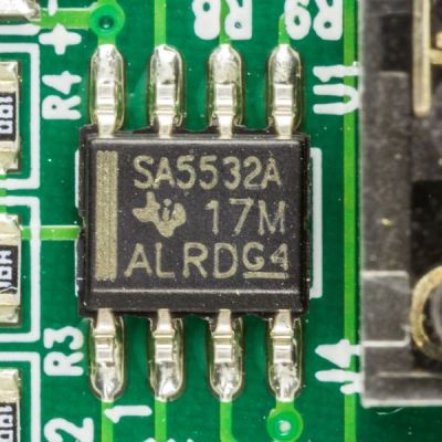
You Can Use LEDs As Sensors, Too

LEDs are a wonderful technology. You put in a little bit of power, and you get out a wonderful amount of light. They’re efficient, cheap, and plentiful. We use them for so much!

What you might not have known is that these humble components have a secret feature, one largely undocumented in the datasheets. You can use an LED as a light source, sure, but did you know you can use one as a sensor?

Continue reading “You Can Use LEDs As Sensors, Too”

This Open Source Active Probe Won’t Break The Bank

If you’re like us, the oscilloscope on your bench is nothing special. The lower end of the market is filled with cheap but capable scopes that get the job done, as long as the job doesn’t get too far up the spectrum. That’s where fancier scopes with active probes might be required, and such things are budget-busters for mere mortals.

Then again, something like this open source 2 GHz active probe might be able to change the dynamics a bit. It comes to us from [James Wilson], who began tinkering with the design back in 2022. That’s when he learned about the chip at the center of this build: the BUF802. It’s a wide-bandwidth, high-input-impedance JFET buffer that seemed perfect for the job, and designed a high-impedance, low-capacitance probe covering DC to 2 GHz probe with 10:1 attenuation around it.

[James]’ blog post on the design and build reads like a lesson in high-frequency design. The specifics are a little above our pay grade, but the overall design uses both the BUF802 and an OPA140 precision op-amp. The low-offset op-amp buffers DC and lower frequencies, leaving higher frequencies to the BUF802. A lot of care was put into the four-layer PCB design, as well as ample use of simulation to make sure everything would work. Particularly interesting was the use of openEMS to tweak the width of the output trace to hit the desired 50 ohm impedance.

Op-Amp Drag Race Turns Out Poorly For 741

When it was first introduced in 1968, Fairchild’s 741 op-amp made quite a splash. And with good reason; it packed a bunch of components into a compact package, and the applications for it were nearly limitless. The chip became hugely popular, to the point where “741” is almost synonymous with “op-amp” in the minds of many.

But should it be? Perhaps not, as [More Than Electronics] reveals with this head-to-head speed test that compares the 741 with its FET-input cousin, the TL081. The test setup is pretty simple, just a quick breadboard oscillator with component values selected to create a square wave at approximately 1-kHz, with oscilloscope probes on the output and across the 47-nF timing capacitor. The 741 was first up, and it was quickly apparent that the op-amp’s slew rate, or the rate of change of the output, wasn’t too great. Additionally, the peaks on the trace across the capacitor were noticeably blunted, indicating slow switching on the 741’s output stage. The TL081 fared quite a bit better in the same circuit, with slew rates of about 13 V/μS, or about 17 times better than the 741, and nice sharp transitions on the discharge trace.

As [How To Electronics] points out, comparing the 741 to the TL081 is almost apples to oranges. The 741 is a bipolar device, and comparing it to a device with JFET inputs is a little unfair. Still, it’s a good reminder that not all op-amps are created equal, and that just becuase two jelly bean parts are pin compatible doesn’t make them interchangeable. And extra caution is in order in a world where fake op-amps are thing, too.

Continue reading “Op-Amp Drag Race Turns Out Poorly For 741”

No Inductors Needed For This Simple, Clean Twin-Tee Oscillator

If there’s one thing that amateur radio operators are passionate about, it’s the search for the perfect sine wave. Oscillators without any harmonics are an important part of spectrum hygiene, and while building a perfect oscillator with no distortion is a practical impossibility, this twin-tee audio frequency oscillator gets pretty close.

As [Alan Wolke (W2AEW)] explains, a twin-tee oscillator is quite simple in concept, and pretty simple to build too. It uses a twin-tee filter, which is just a low-pass RC filter in parallel with a high-pass RC filter. No inductors are required, which helps with low-frequency designs like this, which would call for bulky coils. His component value selections form an impressively sharp 1.6-kHz notch filter about 40 dB deep. He then plugs the notch filter into the feedback loop of an MCP6002 op-amp, which creates a high-impedance path at anything other than the notch filter frequency. The resulting sine wave is a thing of beauty, showing very little distortion on an FFT plot. Even on the total harmonic distortion meter, the oscillator performs, with a THD of only 0.125%.

This video is part of [Alan]’s “Circuit Fun” series, which we’ve really been enjoying. The way he breaks complex topics into simple steps that are easy to understand and then strings them all together has been quite valuable. We’ve covered tons of his stuff, everything from the basics of diodes to time-domain reflectometry.

Continue reading “No Inductors Needed For This Simple, Clean Twin-Tee Oscillator”

Lorenz Attractor Analog Computer With Octave Simulation

[Janis Alnis] wanted to build an analog computer circuit and bought some multiplier chips. The first attempt used apparently fake chips that were prone to overheating. He was able to get it to work and also walked through some Octave (a system similar to Matlab) simulations for the circuit. You can follow along in the video below.

Getting the little multiplier chips into the breadboard was a bit of a challenge. Of course, there are a variety of ways to solve that problem. The circuit in question is from the always interesting [Glen’s Stuff] website.

From that site:

The Lorenz system, originally discovered by American mathematician and meteorologist, Edward Norton Lorenz, is a system that exhibits continuous-time chaos and is described by three coupled, ordinary differential equations.

So, the circuit is an analog solution to the system of differential equations. Not bad for a handful of chips and some discrete components on a breadboard. We’ve seen a similar circuit on Hackaday.io.

Check out our recent competition winners if you want to see op amps do their thing. Analog computers were a thing. They aren’t always that complicated, either.

Continue reading “Lorenz Attractor Analog Computer With Octave Simulation”

Inside A Fake LM358

[IMSAI Guy] got some fake LM358 op-amps. Uncharacteristically, these chips actually performed well even though they didn’t act like LM358s. [IMSAI Guy] did a video about the fake chips and someone who saw it offered to analyze the part compared to a real LM358 to see what was going on. You can see it too in the video below.

A visual inspection made it obvious that the chip was probably a fake. X-ray analysis was a little less obvious but still showed poor quality and different internals. But the fun was when they actually decapsulated the part.

Continue reading “Inside A Fake LM358”

Inside Electronic Gain Control

Normally, if you want to control the gain of an amplifier, you’ll use a variable resistor. You know, like a volume control. But what if you want to control the amplifier’s gain with a voltage? [Engineering Prof] explains a circuit that can do this using a pair of op amps and a pair of matched JFETs.

The analysis is simple because you assume the op amps are not in saturation, so you can assume that the op amp will do what it needs to do to make the input terminals equal. The left-hand op amp has one input grounded, so the output will drive the first FET  to ensure the negative terminal is also 0V. It is easy to see that the current through R1 must then be the current through the FET, which is going to be the control voltage (which is negative) divided by R1.

Continue reading “Inside Electronic Gain Control”