Our hacker [John Duffy] wrote in to let us know about a video he put together to explain the design of his open-source multimeter, the HydraMeter.
If you’re interested in how the circuitry for a voltmeter, ohmmeter, or ammeter might work, this video is a masterclass. In this long and detailed video, [John] walks us through his solutions to various challenges he had while designing his own multimeter. We covered this multimeter last year, and this new video elaborates on the design of the HydraMeter which has been a work in progress for years now.
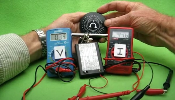
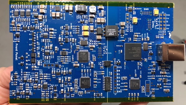
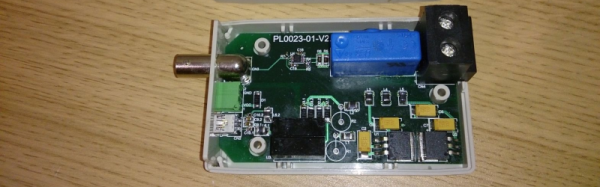
The basic design feeds voltage, current, and resistance front-ends into an Analog to Digital Converter (ADC), which then feeds into a microcontroller and out to the (detachable) display. You can find the KiCad design files on the GitHub page. There is also a write-up on hackaday.io.
The user interface for the meter is… opinionated, and perhaps not to everyone’s taste. In the video, [John] talks a little bit about why he made the UI work the way that it does, and he noted that adding a rotary range switch is a goal for version 2.0.
Thank you, [John], for putting this video together; it is an excellent resource. We look forward to seeing version 2.0 develop soon!
Continue reading “Designing An Open Source Multimeter: The HydraMeter”