Arduino Gear Shift Indicator Finds ‘Em So You Won’t Grind ‘Em

Now, it’s been a shamefully long time since we’ve driven a car with a manual transmission, but as we recall it was pretty straightforward. It certainly didn’t require a lot of help with the shifting pattern, at least not enough to require a technical solution to know what gear you’re in. But then again, we suspect that’s not really the point of [upir]’s latest build.

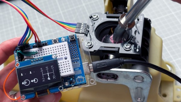
Oh sure, it’s pretty cool to display your current gear selection on a little LCD screen using an Arduino. And [upir] promises a follow-up project where the display goes inside the shifter knob, which will be really cool. But if you take a look at the video below, you’ll see that the real value of this project is the stepwise approach he takes to create this project. [upir] spends most of the time in the video below simulating the hardware and the code of the project in Wokwi, which lets him make changes and tune the design up before committing anything to actual hardware.

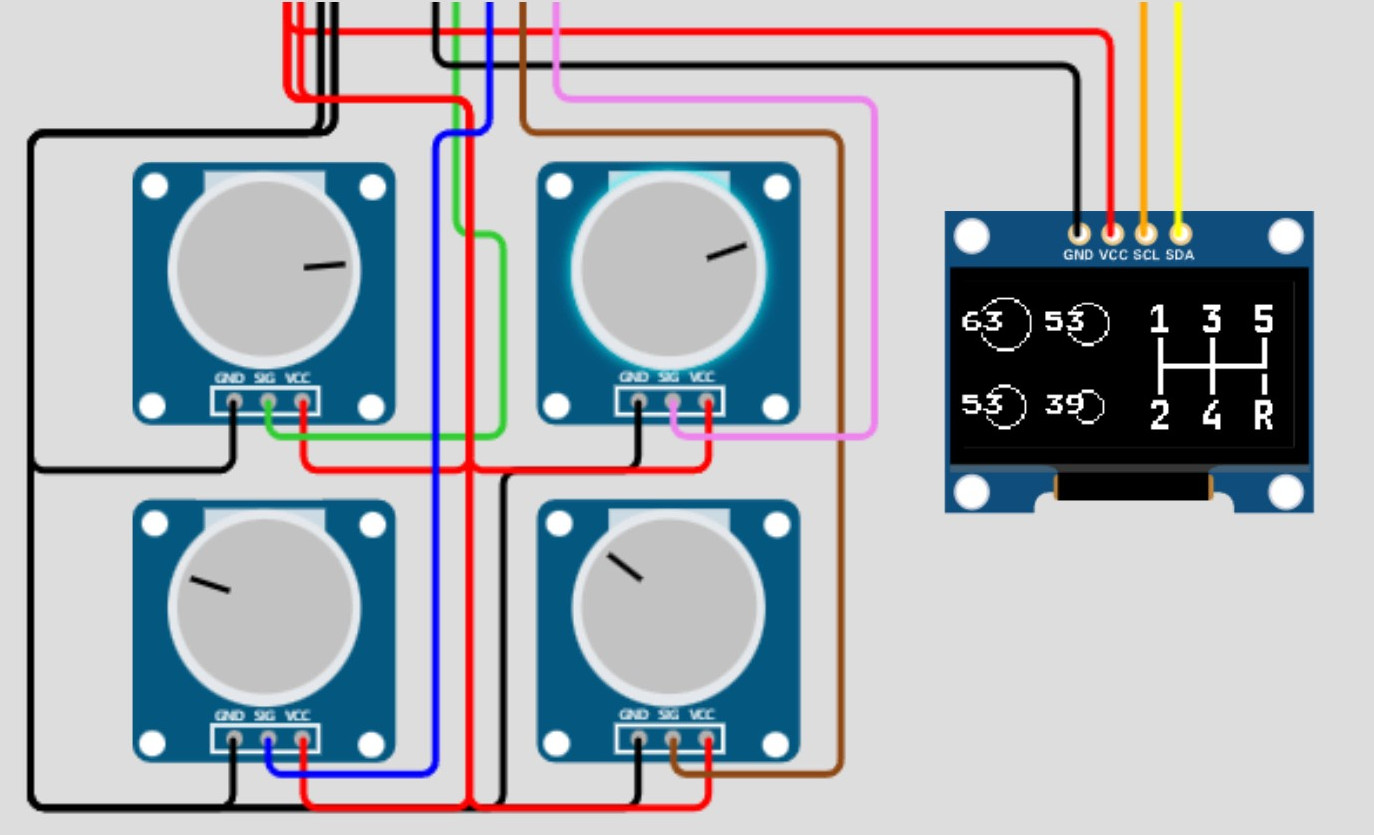
That turned out to be particularly useful with this build since he chose to use analog Hall sensors to detect the shift lever position and didn’t know exactly how that would work. Wokwi let him quickly build a virtual prototype for one sensor (using a potentiometer as a stand-in, since the simulator lacked a Hall sensor model), then quickly expand to the four sensors needed to detect all six gear positions.

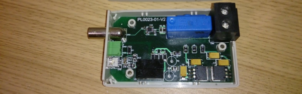
By the time his simulation was complete, the code was almost entirely written. [upir] also walks us through his toolchains for both designing the graphics and laying out the PCB, a non-trivial task given the odd layout. We particularly enjoyed the tip on making smooth curved traces around the oval cutout for the shift lever in the board.

The video below is on the longish side, but it’s chock full of great little tips. Check out some more of [upir]’s work, like his pimped-out potentiometer or his custom animations on 16×2 LCDs.

Continue reading “Arduino Gear Shift Indicator Finds ‘Em So You Won’t Grind ‘Em”

Old Gas Meter Gets Smart With The ESP8266

Measuring the usage of domestic utilities such as water, gas or electricity usually boils down to measuring a repetitive pulse signal with respect to time. To make things easy, most modern utility meters have a pulsed LED output, which can be used to monitor the consumption by using an external optical sensor. But what do you do if your meter isn’t so cooperative?

That’s exactly what [Francesco] had to figure out while developing the non-invasive gas tracking system he calls ESPmeter. His meter might not have an LED, but it did have a magnet attached to the counter disk which activated an internal hall sensor. With some hacking, he was able to attach an external Hall-effect sensor to pick up this magnet and use the signal to monitor his daily gas consumption.


A big stumbling block in such projects is the issue of powering the device for an extended period, and remembering when it’s time to change the batteries. With the clever use of commonly available parts, he was able to reduce power consumption allowing three AA batteries to last about a year between changes. For one thing, he uses an ATtiny13 to actually read the sensor values. The chip doesn’t run continuously, its watchdog is set at 1 Hz, ensuring that the device is woken up often enough so that it has time to power up the sensor and detect the presence of the magnet. Battery voltage is also measured via a voltage divider connected to the chip’s ADC pin.

At regular intervals throughout the day, the ESP8266 polls the ATtiny13 to pull the stored sensor pulses and voltage measurement. Then at midnight, the ESP transmits all the collected data to a remote server. Overall, this whole scheme allows [Francesco] to reliably gather his gas consumption data while not having to worry about batteries until he gets the low voltage notification. Since the data visualization requirements are pretty basic, he is keeping things simple by using Plotly to display his time series data.

If you are unfortunate enough to have an even older meter which doesn’t use optical or magnetic rotation sensing, you can use a disassembled mouse to keep track of the Gas Meter.

Litar: LiDAR air guitar

Litar: An Air Guitar Using LiDAR

This year, [Blecky’s] Hackaday Prize Entry is an air guitar which uses multiple LiDAR sensors to create the virtual strings. What’s also neat is that he’s using his own LiDAR sensor, the MappyDot Plus, an enhanced version of his 2017 Prize Entry, the MappyDot.

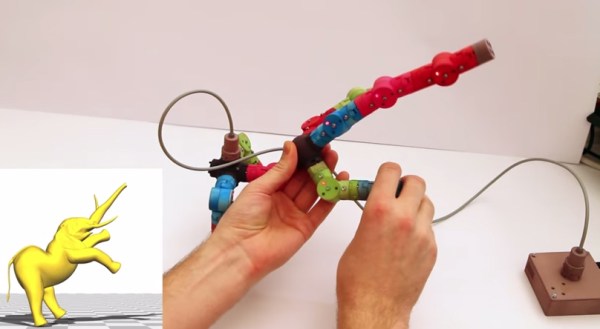
He uses a very clever arrangement of six sensors to get four virtual strings. Each sensor scans a 25-degree field of view. Three adjacent sensors are used to define a string, with the string being in the overlap of the outer two of those sensors. The middle sensor is used for the distance data.

For the chords, he started out using some commercially made joysticks but ran into some ergonomic issues. Also, the manufacturer was discontinuing the product, a no-no for an open source project. So he abandoned that approach and designed his own buttons. He came up with a PCB with a linear hall effect sensor and some springs on it. The button has a magnet attached to its underside and sits on the springs. That way he gets the press and can do vibrato as well.

He plans to use Bluetooth MIDI so that you can play the sound on a phone or laptop but for now he lights up an LED beside each sensor as you press the strings.

Electromagnet-Powered Pendulum

We’re always happy to see hackers inspired to try something different by what they see on Hackaday. To [SimpleTronic] has a project that will let you stretch your analog electronics skills in a really fun way. It’s an electromagnet pendulum analog circuit. Whether you’re building it, or just studying the schematics, this is a fun way to brush up on the non-digital side of the craft.

The pendulum is a neodymium magnet on the head of a bolt, dangling on a one foot aluminium chain. Below, a Hall Effect sensor rests atop an electromagnet — 1″ in diameter, with 6/8″ wire coiled around another bolt. As the pendulum’s magnet accelerates towards the electromagnet’s core, the Hall effect sensor registers an increase in voltage. The voltage peaks as the pendulum passes overhead, and as soon as the Hall Effect sensor detects the drop in voltage, the electromagnet flicks on for a moment to propel the pendulum away. This circuit has a very low power consumption, as the electromagnet is only on for about 20ms!

The other major components are a LM358N op-amp, a CD4001B quad CMOS NOR gate, and IRFD-120 MOSFET. [SimpleTronic] even took the time to highlight each part of the schematic in order to work through a complete explanation.

Continue reading “Electromagnet-Powered Pendulum”

A Very Accurate Current Probe

There’s many different ways of measuring current. If it’s DC, the easiest way is to use a shunt resistor and measure the voltage across it, and for AC you could use a current transformer. But the advent of the Hall-effect sensor has provided us a much better way of measuring currents. Hall sensors offers several advantages over shunts and CT’s – accuracy, linearity, low temperature drift, wider frequency bandwidth, and low insertion loss (burden) being some of them. On the flip side, they usually require a (dual) power supply, an amplification circuit, and the ability to be “zero adjusted” to null output voltage offsets.

[Daniel Mendes] needed to measure some fairly high currents, and borrowed a clip-on style AC-DC current probe to do some initial measurements for his project. Such clip on current probes are usually lower in accuracy and require output DC offset adjustments. To overcome these limitations, he then built himself an invasive hall sensor current probe to obtain better measurement accuracy (Google Translated from Portugese). His device can measure current up to 50 A with a bandwidth stretching from DC to 200 kHz. The heart of his probe is the LAH-50P hall effect current transducer from LEM – which specialises in just such devices. The 25 mV/A signal from the transducer is buffered by an OPA188 op-amp which provides a low output impedance to allow interfacing it with an oscilloscope. The op-amp also adds a x2 gain to provide an output of 50 mV/A. The other critical part of the circuit are the high tolerance shunt resistors connected across the output of the LAH-50P transducer.

The rest of his design is what appears to be a pretty convoluted power supply section. [Daniel] wanted to power his current probe with a 5V input derived from the USB socket on his oscilloscope. This required the use of a 5 V to 24 V boost switching regulator – with two modules being used in parallel to provide the desired output power. A pair of linear regulators then drop down this voltage to +15 / -15 V required for the trasducer and op-amp. His blog post does not have the board layout, but the pictures of the PCB should be enough for someone wanting to build their own version of this current sensor.

Raspberry Pi Controlled Chicken Door

We’re not sure if the Chickens know it yet, but they could be one of the reasons for all this IoT craze now a days. Look for chicken coop, and out come dozens of posts from the Hackaday chest.

Here’s another one from self confessed lazy engineer [Eric]. He didn’t want to wake up early to let his chickens out in the morning, or walk out to the coop to lock them up for the night to protect them from predators like Foxes, Raccoons and Opossum. So he built a Raspberry-Pi controlled chicken coop door that automates locking and unlocking. The details are clear from his video which you can watch after the break. The door mechanism looks inspired from an earlier anti-Raccoon gravity assist door.

The hardware (jpg image) is simple – a couple of hall sensors that detect the open/close status of the coop door that is driven by a DC motor via a bridge controller. The whole setup is controlled using a Raspberry-Pi and this is where the fun starts – because he can now add in all kinds of “feature creep”. Motion sensor, camera, light array, and anti-predator gizmos are all on his drawing board at the moment. Add in your feature requests in the comments below and let’s see if [Eric] can build the most advanced, complicated, gizmo filled chicken coop in the Universe. Combine that with this design, and it could even turn out to be the most beautiful too.

Continue reading “Raspberry Pi Controlled Chicken Door”

3D Real-World Rig

Rigging Your 3D Models In The Real-World

Computer animation is a task both delicate and tedious, requiring the manipulation of a computer model into a series of poses over time saved as keyframes, further refined by adjusting how the computer interpolates between each frame. You need a rig (a kind of digital skeleton) to accurately control that model, and researcher [Alec Jacobson] and his team have developed a hands-on alternative to pushing pixels around.

3D Rig with Control Curves
Control curves (the blue circles) allow for easier character manipulation.

The skeletal systems of computer animated characters consists of kinematic chains—joints that sprout from a root node out to the smallest extremity. Manipulating those joints usually requires the addition of easy-to-select control curves, which simplify the way joints rotate down the chain. Control curves do some behind-the-curtain math that allows the animator to move a character by grabbing a natural end-node, such as a hand or a foot. Lifting a character’s foot to place it on chair requires manipulating one control curve: grab foot control, move foot. Without these curves, an animator’s work is usually tripled: she has to first rotate the joint where the leg meets the hip, sticking the leg straight out, then rotate the knee back down, then rotate the ankle. A nightmare.

[Alec] and his team’s unique alternative is a system of interchangeable, 3D-printed mechanical pieces used to drive an on-screen character. The effect is that of digital puppetry, but with an eye toward precision. Their device consists of a central controller, joints, splitters, extensions, and endcaps. Joints connected to the controller appear in the 3D environment in real-time as they are assembled, and differences between the real-world rig and the model’s proportions can be adjusted in the software or through plastic extension pieces.

The plastic joints spin in all 3 directions (X,Y,Z), and record measurements via embedded Hall sensors and permanent magnets. Check out the accompanying article here (PDF) for specifics on the articulation device, then hang around after the break for a demonstration video.

Continue reading “Rigging Your 3D Models In The Real-World”