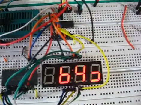
Bigtime is a simple way to create an auxiliary display for the Beat707 MIDI controller. The right half of the display shows the beat pattern that the drum machine is using, while the left half keeps track of the current measure.
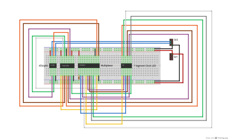
Just a few components went into the extra hardware. A four-digit seven segment display is fed data from an ATtiny85. Since that microcontroller has only eight pins, a 595 shift register and CD4067 take care of translating serial data into the outputs necessary to light the display. The entire thing connects to the Beat707’s I2C bus, which means you don’t need to make hardware alterations to the original, and this leaves plenty of room for more addons.
The code package includes a Fritzing file, but for your convenience we’ve embedded a PNG of the hardware connections after the break. You’ll also find the demo video where [Guilherme] explains how this works.
[youtube=http://www.youtube.com/watch?v=xhpI_UP6tjY&w=470]


In case anyone wonders, SV3 and SV1 are headers on the Beat707 PCB. Also, the GitHub files includes everything you need to flash the ATtiny85 chip, so no googling for messy libraries and tutorials, its all there.
Sniffs the i2c bus real time for the data? Or is it a i2c master?
BigTime uses I2C Slave Mode. Beat707 them just sends data out and BigTime reads it to know what to do. Is that what you asked?
Frankly, I don’t understand why people insist on using 8 pin microcontrollers in combination with excessive external circuitry when you can get a microcontroller with sufficient amount of pins for basically the same money.
@Svofski, well, in this case, I had the cheap ATtiny85 at hand, and also the C595 and CD4067 also at hand doing nothing. Plus, more pins wouldn’t help me that much, as I would still need 6 transistors as this LED Clock is common voltage, not ground, so each LED segment needs ground to turn on, which an output PIN from an ATmega328, for instance, wouldn’t work. ;-) In any event, it was more a “lets see if I could make this work with all my spare parts” thing. ;-) Still, it turns out to be OK, I still want to get it working correctly with transistors, as it would be much brighter, but that’s for another time.
@beat707 I thought the midi controller was a commercial off the shelf product.
@Beat707: it’s okay to use junk that you have at hand, don’t get me wrong :) I didn’t understand though, why an output pin on an atmega wouldn’t work? CMOS logic is equally capable of draining and sinking. If you output a “0” to a port, you’re effectively “grounding the pin”, same as you’re “+V”-ing the pin by outputting a “1” to it. Better yet, you can almost completely disengage it from your circuit by making it an input, or high impedance.
@Svofski, thanks, I will check how to drain from a pin, that would help a lot indeed. :-)
@cde, Beat707 itself is a DIY product, but you can buy an assembled unit from Rugged Circuits, (no case) the software is open-source.