Wrist Welcomes Wii Nunchuk As Gloriously Ergonomic Macropad

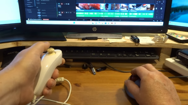
[John Dingley] spends a lot of time editing videos, and as many of us know, when it comes to repetitive tasks the more ergonomic the better.

Keyboard shortcuts exist for common video editing functions, but [John] found that the vast majority of his work needed only three or four of them. Feeling he could do better than a three-key macropad, he turned to what’s perhaps one of the most ergonomic devices ever designed — the Wii Nunchuk.

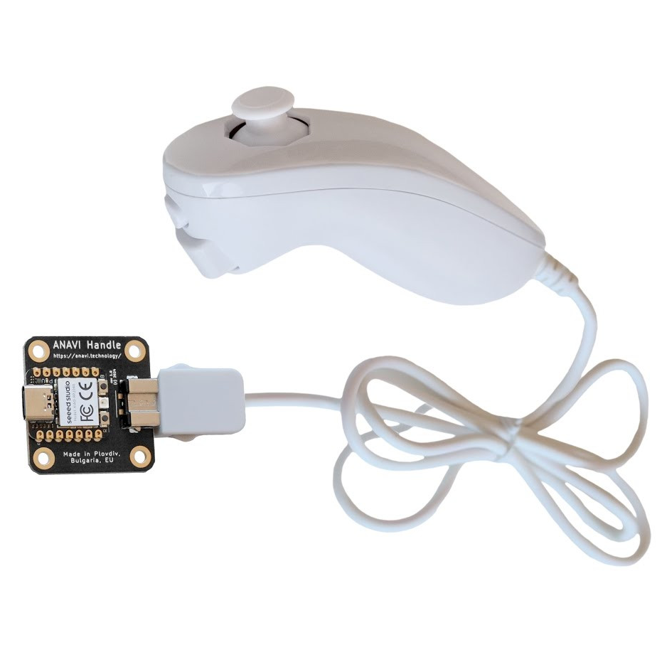
A Wii Nunchuk is an I2C device, so there needs to be some intermediary device involved if you want to plug it into a computer. [John] solves that with the ANAVI Handle, an open source adapter to make a Nunchuk act like a USB Human Interface Device (HID). That addresses the connectivity problem, but the default firmware on the adapter only treats the Nunchuk as a mouse or joystick, so a few more changes are required before it can be pressed into service as an ultra-comfortable macropad.

The ANAVI Handle runs CircuitPython code on an RP2040, and modifying its behavior is as simple as plugging it in via USB and editing the code right on the device. One has to define some keyboard events, configure the device to act as a keyboard, and send the right events when the buttons or joystick get pushed. [John] provides the code, and walks through the changes on video so even those without any coding experience can get it done.

The Nunchuk design is still being sold and used today, and it’s shown up in all kinds of places. We’ve seen a Bluetooth-enabled one and even seen a Raspberry Pi Zero shoehorned into one, complete with HDMI output.

Continue reading “Wrist Welcomes Wii Nunchuk As Gloriously Ergonomic Macropad”

Addressable LEDs Make Giant 16×2 Character Display

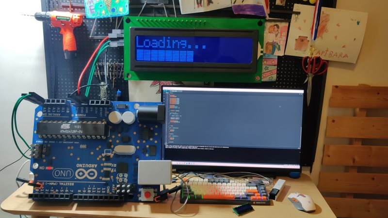
We’ve always taken a certain childlike joy in seeing tiny things made big, and big things tiny. Evidently [Uncle Stem] is the same way, if this 7x sized 16×2 “LCD” display is any indicator.

“LCD” is in scare quotes there, because while the original display is a character LCD, [Uncle Stem]’s embigginated recreation is not. Liquid crystal displays are beyond all but the most dedicated DIYers, so [Stem] recreated the whole thing with addressable LEDs instead — over a thousand of them. Each character got its own PCB, and rather than pay for assembly [Stem] used a 3D printed stencil to help apply solder paste, an idea we’ve seen before. His choice of long lengths of nickel strip — the stuff you spot weld to Li-ion batteries — to join the LED-holding PCBs is also worth noting.

In order to get his giant display to act like the I2C-operated module he loves, [Uncle Stem] equipped it with an RP2040 pre-programmed with the LCD character set. That way he can plug it into any Arduino project that uses the LiquidCrystal_I2C library and have the authentic 1602 experience. The green “PCB” the display is mounted to is actually laser-cut plywood, while some acrylic sits in front of his PCBs with office paper to act as as a diffuser. A 3D printed frame completes the illusion. He even goes so far as to replicate the pin headers at 7:1 scaling with brass rods.

He also connects it to a over-sized Arduino, with giant jumper wires. But for the record, not the giant Arduino we featured previously. Like we said, hackers like to mess with scale, and we’ve seen everything from giant benchies to a working Mac Classic for Barbie.

Continue reading “Addressable LEDs Make Giant 16×2 Character Display”

Pi Pico Puts Bluetooth Keyboards On The I2C Bus

If you’ve ever worked with I2C, you know its one of those things that makes working with modern microcontrollers such a pleasure. With a few wires and not many more lines of code, you can communicate with all sorts of hardware such as sensors, displays, and input devices. There are even I2C keyboards out there, although they tend to be a bit pokey — and not in the good way as it pertains to keyboards.

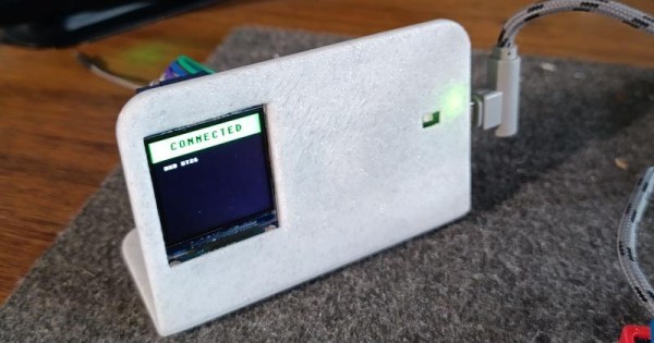
But the bt2i2c project from [Roberto Alsina] promises to improve things. With his firmware flashed to a Pi Pico W, you can establish a connection with any standard Bluetooth keyboard and have the keystrokes sent over the wire via I2C. As far as your project is concerned, the input will appear to be coming from a BlackBerry BBQ20/BBQ10 keyboard using the address 0x1F, which means that there’s already plenty of code out there to work with. While [Roberto] explains its not strictly necessary, connecting a ST7789 display to the Pi Pico over SPI will give you some visual feedback on connection status.

As microcontrollers become increasingly powerful and capable of the sort of thing we would once have done on a “real” computer, a project like this has some fascinating potential. We’ve seen a number of “writerdeck” projects running on chips like the ESP32, and it’s not hard to see the appeal of being able to easily pair your favorite Bluetooth keyboard up to one of them.

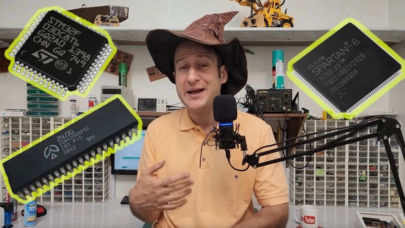
Electronic Wizard in his lab wearing his wizards hat

How To Use The AT24C32 EEPROM For 4KB External Memory For Microcontrollers

Over on YouTube [Electronic Wizard] explains how to use the AT24C32 EEPROM for external memory for microcontrollers.

He begins by explaining that you don’t want to try modifying your microcontroller flash memory for storing settings, you want to use a separate EEPROM for that. Sometimes your microcontroller will have EEPROM memory attached, but you might still find yourself needing to attach more. The AT24C32 EEPROM is a 4KB non-volatile memory chip. It’s available in various 8-pin packages and two voltage levels, either 2.7 to 5.5 volts or 1.8 to 5.5 volts, and it’s programmed using the I2C protocol.

Continue reading “How To Use The AT24C32 EEPROM For 4KB External Memory For Microcontrollers”

Pi Port Protection PCB

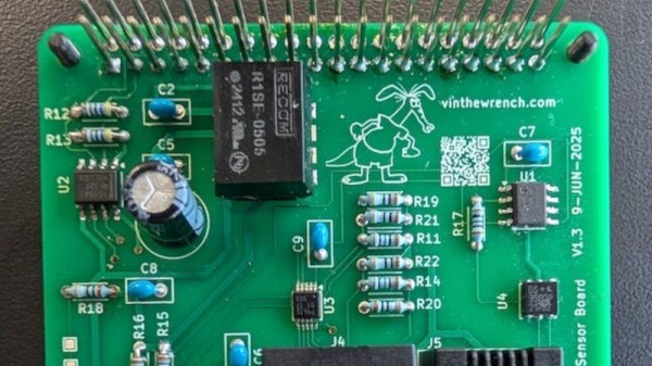
We’re used to interfaces such as I2C and one-wire as easy ways to hook up sensors and other peripherals to microcontrollers. While they’re fine within the confines of a small project, they do have a few limitations. [Vinnie] ran straight into those limitations while using a Raspberry Pi with agricultural sensors. The interfaces needed to work over long cable runs, and to be protected from ESD due to lightning strikes. The solution? A custom Pi interface board packing differential drivers and protection circuits aplenty.

The I2C connection is isolated using an ISO1541 bus isolator from TI, feeding a PCA9615DP differential I2C bus driver from NXP. 1-wire is handled by a Dallas DS2482S 1-wire bus master and an ESD protection diode network. Even the 5-volt power supply is delivered through an isolated module.

Whether or not you need this Raspberry Pi board, this is still an interesting project for anyone working with these interfaces. If you’re interested, we’ve looked at differential I2C in the past.

Moving Software Down To Hardware

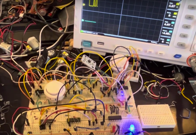
In theory, any piece of software could be built out of discrete pieces of hardware, provided there are enough transistors, passive components, and time available. In general, though, we’re much more likely to reach for a programmable computer or microcontroller for all but the simplest tasks for several reasons: cost, effort, complexity, economics, and sanity. [Igor Brichkov] was working with I2C and decided that he wanted to see just where this line between hardware and software should be by implementing this protocol itself directly with hardware.

One of the keys to “programming” a communications protocol in hardware is getting the timing right, the first part of which is initializing communications between this device and another on the bus. [Igor] is going to be building up the signal in parts and then ORing them together. The first part is a start condition, generated by one oscillator and a counter. This also creates a pause, at which point a second oscillator takes over and sends data out. The first data needed for I2C is an address, which is done with a shift register and a counter pre-set to send the correct bits out on the communications lines.

To build up the rest of the signal, including data from the rotary encoder [Igor] is using for his project, essentially sets of shift registers and counters are paired together to pass data out through the I2C communications lines in sequence. It could be thought of that the main loop of the hardware program is a counter, which steps through all the functions sequentially, sending out data from the shift registers one by one. We saw a similar project over a decade ago, but rather than automating the task of sending data on I2C it allowed the user to key in data manually instead.

Continue reading “Moving Software Down To Hardware”

I2C Sniffing Comes To The Bus Pirate 5

While the Bus Pirate 5 is an impressive piece of hardware, the software is arguably where the project really shines. Creator [Ian Lesnet] and several members of the community are constantly working to add new features and capabilities to the hardware hacking multi-tool, to the point that if your firmware is more than a few days old there’s an excellent chance there’s a fresher build available for you to try out.

One of the biggest additions from the last week or so of development has been the I2C sniffer — a valuable tool for troubleshooting or reverse engineering devices using the popular communications protocol. [Ian] has posted a brief demo video of it in action.

It’s actually a capability that was available in the “classic” versions of the Bus Pirate, but rather than porting the feature over from the old firmware, [Ian] decided to fold the MIT licensed pico_i2c_sniffer from [Juan Schiavoni] into the new codebase. Thanks to the RP2040’s PIO, the sniffer works at up to 500 kHz, significantly outperforming its predecessor.

Admittedly, I2C sniffing isn’t anything you couldn’t do with a cheap logic analyzer. But that means dealing with captures and making sure the protocol decoder is setup properly, among other bits of software tedium. In comparison, once you start the sniffer program on the Bus Pirate 5, I2C data will be dumped out to the terminal in real-time for as long as you care to see it. For reverse engineering, it’s also very easy to move quickly from sniffing I2C packets to replaying or modifying them within the Bus Pirate’s interface.

If you already have a Bus Pirate 5, all you need to do is flash the latest firmware from the automated build system, and get sniffing. On the fence about picking one up? Perhaps our hands-on review will help change your mind.