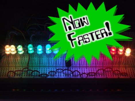
Community collaboration is a great thing. Take the Arduino PWM library for shift registers. Some folks at the Arduino forum pitched in and helped [Elco] trim off a bunch of clock cycles by using the Rotate Over Carry instruction. Now he’s reduced the overhead per shift-register from 108 down to just 43. So far this doesn’t mean more possible outputs – 768 is still quite a lot – but does it means better precision when max outputs are used. This effectively doubles the brightness levels for 768 LEDs from 16 up to 32.
We’re at a loss for what to link to here. [Elco] has a new page for the library. There’s the original forums thread but we didn’t see much of interest there. We found some stuff in the comments of this Reddit post. And of course, if you have no idea what we’re talking about go back and read the original feature.


“ShiftPWM computes the outputs in a timer interrupt and uses the SPI to control the shift registers as fast as possible.”
Finally. Hardware SPI.
Hmmm…. Ya know this could help improve the large LED dance floor that we have seen before. Now that you have a few more brightness levels you can really dither a smooth, trippy floor
LOWCOST AMBILIGHT!
Best is to link here:
elcojacobs.com/shiftpwm
There is an introduction there and a link to google code. I will add a link to the Arduino forum for support questions.
Maybe it’s just too early for me, but what do you mean by “This effectively doubles the brightness levels for 768 LEDs from 16 up to 32.”? What unit of measurement are we talking about?
@anon:no unit of measurement, i dont think. just more granularity in the light output.
Not true. He more than halved the clock cycles used. The unit of measure is “clock cycles” (synonymous with “time” in this case.)
With PWM the brightness is varied by turning the light on for an amount of time and off for an amount of time (very small amounts of time, ideally ones that are not perceptible to humans.) The amount of time it’s on is called “duty cycle.”
With the code taking less time doing random shift register setup, more time can be devoted to duty cycles, thus giving brighter lights.
#facepalm. Apologies. I read the article AND your question wrong.
First off you were asking about the unit of measurement used for 16 and 32: Yeah that’s arbitrary shades of brightness.
So before it had 1/16 granularity (so where 0 is off and 1 is on, it would be toggled in .06, .13, .19, etc… 16 positions between off and on, inclusively) and now it has 1/32 granularity (so 32 positions between off and on, .03, .06, .09, .13, etc…)
Secondly, I had read the sentence wrong, thinking the duty cycle time had increased for a higher brightness than before — while this is potentially the case, the article does not imply it. Apologies again, lol.
@anon that means that the from 0 to maxi brightness you get 32 levels.
What this means is that each led can display 32x32x32 = 32.768 distinct colors.
@Bogdan and dext3r:
You are correct. The post should have said number of brightness levels for clarity.
32 levels is if you want 768 outputs.
For less outputs, you can easily get 256.
For 6 shift registers, 75 Hz, 256 levels, the load is 0.45
Nice to see all the interest into this subject! A lot of people are controlling lighting with Arduino so this is very welcome. SPI is really the right way as it is done now.
I’ll post my tip about Binary/Bit Code Modulation once more. You can have 256 levels with just 8 shift register updates (one for each bit) in a time slot instead of the 256. That is a 32 fold decrease. And you really need at least the 256 levels if you want to get nice dimming and color changes. And 100Hz won’t hurt either.
If I have some time to kill, I’ll add ShiftBCM.
Shouldn’t cost me much time.
I’m new to this Shift register stuff, Just grabbed 20 of those 74HCT595’s from ebay, I gotta try this.
Thanks for the great info.
Has anyone brought out the point that using regular 74HCT595 shift register is actually a bad design as you are forcing it to drive harder then it’s rated for?
Yes, each IO is rated for 20mA, but supply/GND current is only rated to 70 mA. All outputs on would be 160 mA with 20mA LEDs. 160 > 70
I suggest a TLC5916 instead, and it has built in Constant Current driver, so you don’t need to add resistors in series with each LED.