Automation For The NES

Old hardware might not be anywhere close to as powerful as modern technology, but it does have a few perks. Aesthetics can of course drive the popularity of things like retro gaming systems, but the ease of understanding the underpinnings of their inner workings is also critical. The Nintendo Entertainment System, now nearly four decades old, is a relatively simple machine by modern standards and this lends the system to plenty of modifications, like this controller that allows the system to be somewhat automated.

The original NES controller used a fairly simple shift register to send button presses to the system. The system outputted a latch signal to the controller, the shift register would take as input the current state of the buttons, and then would send them one-by-one to the system at a rate of around 1000 times per second. These signals can be sent without a controller easily enough, too. This build uses a CD4021 shift register, which is the same as the original controller, but instead of reading button states it accepts its inputs from a separate computer via a latching circuit. In this case, the separate computer is a custom design that came about through adapting cassette storage for a 6502-based computer, but it could come from anything else just as easily.

With this system in place, it’s possible to automate gameplay to some extent. Since the system can’t get feedback about the game in its current state, it requires some precise timing to get it to play the game well, and a lot of tuning needs to go into it. This isn’t just a one-off, either. Similar methods are how we get tool-assisted speedruns of games and although these are often done in emulators instead of on real hardware, they can result in some interesting exploits.

Continue reading “Automation For The NES”

[Ken Shirriff] Takes A Bite Of The Apple-I

The Apple-I was a far cry from Apple’s later products. A $666 single-board computer, the product had some unique design features including using a shift register for video memory to save money. The shift registers of the day required high-current clock pulses that ranged from -11 to 5V and there was a DS0025 clock driver chip to handle the job. [Ken Shirriff] takes the unusual chip apart for us in a recent blog post.

The use of a shift register as memory isn’t a new idea. Really old computers like EDSAC used mercury delay lines as memory which was essentially a physical shift register. In those cases, the ALU and other processing only had to deal with a bit at a time, further simplifying things. For the Apple, there were seven shift registers to store 6-bits of display data and a cursor position. The 6 bits of character data drove — indirectly — a character generator ROM to convert the data into dots for the display.

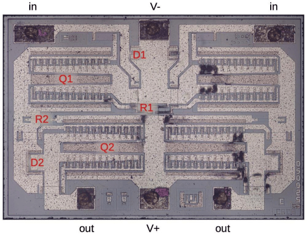
Driving all those shift register flip flops requires a lot of clock current, so the DS0025 uses an unusual transistor design. There are 24 separate emitters in two groups. It acts like a large transistor, but you could also consider it as two 12-emitter transistors or 24 separate transistors in parallel. The metal wiring, interestingly enough, tapers because at the start of the conductor, the current for all 12 sub-transistors flows, but by the end, it is only the current for the last sub-transistor, so the conductor doesn’t have to be as wide. In addition, the two transistors have to have matched resistance which requires careful design so the transistors turn on at the same time.

The final result is an inverter that can provide 1.5 amps. This current helps overcome the relatively large capacitance in the shift register’s clock line. The clock rate was 1 MHz and the load capacitance was about 150 picofarads.

We enjoy [Ken’s] posts ranging from mysteries to space hardware. It is always interesting to see what is inside these devices or, at least, what was in the old devices we’ve all seen.

Spectrum Display Uses Tiny CPU And Many LEDs

You would think the hard part about creating a spectrum analyzer using a pint-sized ATTiny85 would be the software. But for [tuenhidiy], we suspect the hard part was fabricating an array of 320 LEDs that the little processor can drive. The design does work though, as you can see in the video below.

The key is to use a TPIC6B595N which is an 8-bit shift register made to drive non-logic outputs. With all outputs on, the driving FETs can supply 150 mA per channel and the device can handle 500 mA per channel peak. At room temperature, the part can go over 1W of total power dissipation, although that goes down with temperature, of course. If you need higher power, there’s a DW-variant of the part that can handle a few hundred milliwatts more.

Continue reading “Spectrum Display Uses Tiny CPU And Many LEDs”

Apollo Shift Register Is Discrete

We’re unabashed fans of [Ken Shirriff] here at Hackaday, and his latest post about an Apollo-era transistorized shift register doesn’t disappoint. Of course, nowadays a 16-bit shift register is nothing special. But in 1965, this piece of Apollo test hardware weighed five pounds and likely cost at least one engineer’s salary in the day, if not more.

The incredible complexity of the the Apollo spacecraft required NASA to develop a sophisticated digital system that would allow remote operators to execute tests and examine results from control rooms miles away from the launch pad.

This “Computer Buffer Unit” was used to hold commands for the main computer since a remote operator could not use the DSKY to enter commands directly. Externally the box looks like a piece of military hardware, and on the inside has six circuit boards stacked like the pages of a book. To combat Florida’s notoriously damp conditions, the enclosure included a desiccant bag and a way to fill the device with nitrogen. A humidity indicator warned when it was time to change the bag.

There is a lot more in the post, so if you are interested in unusual construction techniques that were probably the precursor to integrated circuits, diode transistor logic, or just think old space hardware is cool, you’ll enjoy a peek inside this unusual piece of gear. Be sure to check out some of [Ken]’s previous examinations, from tiny circuits to big computers.

Decoding The PS/2 Keyboard Protocol Using Good Old Fashioned Hardware

1987 was a glorious year.  It brought us the PS/2 keyboard standard that’s still present on many a motherboard back panel to this day. (It also marked the North America/Europe release of The Legend of Zelda but that’s another article.) Up until this point, peripherals were using DIN-5 and DE-9 (often mistakenly called DB9 and common for mice at the time) connectors or — gasp — non-standard proprietary connectors. So what was this new hotness all about? [Ben Eater] walks us through the PS/2 hall of fame by reverse-engineering the protocol.

The PS/2 connector in all its glory

This is a clocked data protocol, so a waveform is generated on the data pin for each key pressed that can be compared to the clock pin to establish the timing of each pulse. Every key sends a unique set of encoded pulses and voila, the whims of the user can quickly and easily be decoded by the machine.

This is where [Ben’s] dive really shines, we know he’s a breadboarding ninja so he reaches for some DIP chips. A shift register is an easy way to build up a parallel PS/2 interface for breaking out each data packet. There are a few quirks along the way, like the need to invert the clock signal so the shift register triggers on the correct edge. He also uses the propagation delay of a couple inverter gates to fire the 595 shift register’s latch pin slightly late, avoiding a race condition. A second 595 stores the output for display by a set of LEDs.

Beyond simply decoding the signal, [Ben] goes into how the packets are formatted. You don’t just get the key code, but you get normal serial interface error detection; start/stop bits and a parity bit as well. He even drills down into extended keys that send more than one packet, and a key-up action packet that’s sent by this particular keyboard.

This is the perfect low-level demo of how the protocol functions. On the practicality side, it feels a bit strange to be breaking out the serial to parallel when it would be very easy to monitor the two signal lines and decode them with a microcontroller. You might want to switch it up a bit, stick with the clock and data pins, but connect them to a Raspberry Pi using just a few passive components.

Continue reading “Decoding The PS/2 Keyboard Protocol Using Good Old Fashioned Hardware”

Discrete-Logic UART Keeps 8-Bit TTL Computer Connected

Pity the poor TTL computer aficionado. It’s an obsession, really — using discrete logic chips to scratch-build a computer that would probably compare unfavorably to an 80s era 8-bit machine in terms of performance. And yet they still forge ahead with their breadboards full of chips and tangles of wire. It’s really quite beautiful when you think about it.

[Duncan] at Shepherding Electrons has caught the TTL bug, and while building his 8-bit machine outfitted it with this discrete logic UART. The universal asynchronous receiver-transmitter is such a useful thing that single-chip versions of the device have been available since the early 1970s. [Duncan]’s version makes the magic of serial communications happen in just 12 chips, all from the 74LS logic family.

As if the feat of building a discrete logic UART weren’t enough, [Duncan] pulled this off without the aid of an oscilloscope. Debugging was a matter of substituting the 2.4576 MHz crystal oscillator clock with a simple 1 Hz 555 timer circuit; the reduced clock speed made it easier to check voltages and monitor the status of lines with LEDs. Once the circuit was working, the full-speed clock was substituted back in, allowing him to talk to his 8-bit computer at up to 38,400 bps. Color us impressed.

For more TTL computer goodness, and to see where [Duncan] got his inspiration, check out [Ben Eater]’s many discrete logic projects — his scratch-built 6502, a low-end video card, or even his take on serial communications.

Matrix Of Resistors Forms The Hot Hands Behind This Thermochromic Analog Clock

If you’re going to ditch work, you might as well go big. A 1,024-pixel thermochromic analog clock is probably on the high side of what most people would try, but apparently [Daniel Valuch] really didn’t want to go to work that day.

The idea here is simple: heat up a resistor by putting some current through it, lay a bit of thermochromic film over it, and you’ve got one pixel. The next part was not so simple: expanding that single pixel to a 32 by 32 matrix.

To make each pixel square-ish, [Daniel] chose to pair up the 220-ohm SMD resistors for a whopping 2,048 components. Adding to the complexity was the choice to drive them with a 1,024-bit shift register made from discrete 74LVC1G175 flip flops. With the Arduino Nano and all the other support components, that’s over 3,000 devices with the potential to draw 50 amps, were someone to be foolish or unlucky enough to turn on every pixel at once. Luckily, [Daniel] chose to emulate an analog clock here; that led to additional problems, like dealing with cool-down lag in the thermochromic film when animating the hands, which had to be dealt with in software.

We’ve seen other thermochromic displays before, including recently with this temperature and humidity display. This one may not be the highest resolution display out there, but it’s big and bold and slightly dangerous, and that makes it a win in our book.