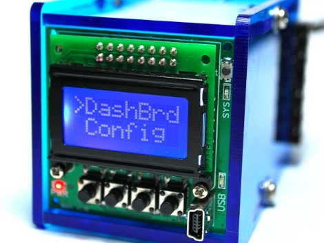
Need PID control in your next project? Perhaps this little beauty can help. It’s an Open Source PID controller that also follows the Open Hardware guidelines. [Brett Beauregard] based the project on the newly minted Arduino PID library which he wrote. In the video after the break [Brett] takes apart the device, walking through some of the ways this might be hacked. If you want an overview of every part of this project to-date the best resource is probably his personal blog post.
The front circuit board is the meat and potatoes of the device. It hosts the user interface in the form of buttons, LEDs, and a graphic LCD screen. You can also see the USB mini-b connector which gives you access to the Arduino compatible ATmega328 microcontroller on the back. There is also a piezo buzzer for your alarm needs.
The prototype that [Brett] shows off uses pin connectors to join the main board to the two daughter boards. Unfortunately, the production model moved to dual-sided edge connectors. That’s fine if you you’re using it in its stock condition, but it makes it a bit harder to replace those boards with your own hardware. None-the-less, we love to see great Open Hardware projects brought to market![youtube=http://www.youtube.com/watch?v=n768MXEESUo&w=470]


Just the thing to replace my Omron E5CK controllers. expensive but just excellent. This looks better.
I’d be a bit worried if I replaced that tried and true pro Omron controller with this awesome (and I mean it!), cute but still very much a DIY Arduino clone and used it with anything that can either blow up (say, deals with compressed air at serious pressure) or go up in flames or, to be honest, just simply runs unattended for a long time.
Anything else that requires a gentle warm up or at least does not have enough energy to tear a limb off, it’d be fun to play with this one for sure!
Agreed. This thing needs to be run through the gauntlet for a year or two AT LEAST before I’d even think of suggesting mission-critical use.
1. That is a character display, not a graphical display.
2. He mentions a DB9 connector twice at the start of the video but I’m pretty sure there is no DB9 connector there.
@weknow there’s a simple explanation here: I did not eat my wheaties.
it’s an 8×2 character display, and for god knows what reason I called a freaking 5.5mm power plug a DB9 connector.
added some comments to the video. thanks.
Good reply. Well done.
Very nice. I have an Auber Instruments ramp/soak PID controller I’m using for a reflow oven, but it doesn’t allow me to set time intervals less than 1 minute (not great for the peak of the reflow curve). I think I’ll have to order one of these and sell the old PID controller.
Very nice project, though having the front panel a PCB just hanging out there looks pretty bad. Enclosing a project can be hard, but IMO it’s not done until it’s in a box.
yeah that front is a pretty tough topography to cover while staying true to the form factor. if we ever get to an injection molded case a front will certainly be part of it.
right now I think it screams “look at me! I’m open as hell! you know you want to hack me” which is certainly of some value.
One of the best products I’ve seen in a good long time. Well documented, great video, a real case, well though out.
Hats off to you!
BTW – could you not squeeze a SSR in to the case?
we’re thinking about it. that’s one of the reasons we tried to maximize the payload area using card-edge connectors. for this initial release however, a relay just made the most sense. cost, sourcing and size… it was worth a few clicks.
if you really want an SSR there’s always the option of bypassing the relay and sending a digital output to a 40A crydom or something.
PID – Pelvic inflammatory disease
Now they have a opensource version of the disease?
Seems a little off field for Hack-a-day.
I truly believe that open source genetic design will be the death of us all.
..and I hope it happens soon because I’m gonna have a blast.
…um…with the whole genetic development thing..n-not the whole ‘we gonna die!’ thing.
Whoa, cool!
I like the modularity on input/output boards, as well as the selected daugherboard connector.
4-20mA current communication is more or less standard in the proprietary side, so those I/O would allow interfacing with commercial off the shelf sensors and actuators.
I’m sure someone out there is right now hacking together said boards :)
Awesome. Now I can make my cron-based tweeting sous vide cooker. w00t
need PID only, no need for thermocoupler.
Could anybody refer the site where I can get this pid
Dropped an earlier version of Brett’s PID library on an Arduino to control a sous-vide cooker — couldn’t praise it more!