3D printing has had its time to spread its wings into the everyday home, yet many of those homes lack the proper ventilation to prevent the toxic VOCs from escaping. Because of this, [Clura] has put together an entire open-sourced smart enclosure for most open concept printers.
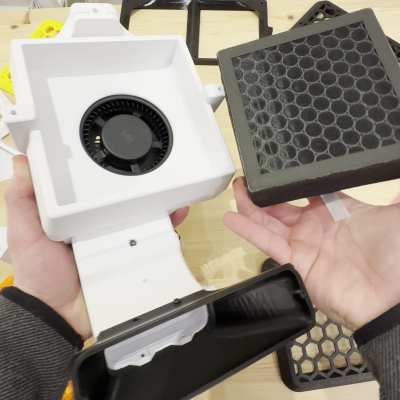
While certain 3D printers or filament choices lend themselves to being worse than others, any type of plastic particles floating around shouldn’t find their way into your lungs. The [Clura] enclosure design includes HEPA and carbon filters in an attempt to remove this material from the air. Of course, there’s always the choice to have a tent around your printer, but this won’t actually remove any VOCs and air located inside a simple enclosure will inevitably escape.
What makes this enclosure different from other, either commercial or open-source designs, is the documentation included with the project. There are kits available for purchase, which you may want for the custom PCB boards for smart features such as filament weighing or fume detection. Even still, if you don’t want to purchase these custom boards the Gerber files are available on their GitHub page.
As smart as this enclosure is, it still won’t fix the issues of what happens to the toxins in your print after it’s done printing. If you are interested in this big picture question, you are not alone. Make sure to stay educated and help others learn by checking out this article here about plastic in our oceans.