At Hackaday, we’ve seen enclosures built out of just about every material. From wood, glass, epoxy resin, plastic, and even paper, all these different types of enclosures provide some interesting properties. Sometimes, though, you need an enclosure made out of metal and welding together steel cases isn’t exactly easy or cheap. [manekinen] came up with a really great solution to the problem of welding together sheet metal. It’s a very easy to build spot welder perfect for fabbing steel cases.
The core of the build is a transformer pulled from a Technics stereo amplifier. [manekinen] removed the stock secondary winding and rewound the transformer four turns of 35mm ² wire (about 2 AWG). This made the transformer put out 2.6 Volts a 1 kA – more than enough to weld 22 ga sheet.
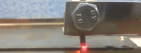
For the control mechanism, [manekinen] put a limit switch on the electrode arm and wired that to a timer. A knob on the front of the welder allows him to vary the time the welder is on from 0 seconds to 4 seconds.
The results are fantastic – trying to rip apart a weld only results in the metal itself tearing; exactly what you want to see in a welder. It’s a great build made even more fantastic by the welder building its own enclosure.
[youtube=http://www.youtube.com/watch?v=1cgz1T8AcNY&w=470]


Nice build. Too bad he used yellow/green wire, this color code is reserved for earth and suppose to be safe. Now he’s running 1kA through it…
Some people will just say: “copper is copper”, in that case its all the same. Too bad the fun will end when someone gets electrocuted…
Well, when you build your own, you can use proper coloured wires :)
Color codes aren’t used for the convenience of those who built the gadget: they are there to ensure the safety of those who didn’t.
When will HAD post an easy-to-build DIY welder that can be used to weld jump rings for chainmaille? Aluminium, steel, iron, or titanium.
We’ll do that once we can find a place to get easily sourced and modified (and cheap) transformers.
I want to build one, but using a very custom part in a tutorial build doesn’t make a whole lot of sense.
microwave oven transformers.
Hello, i’d rather say “current is current”. It doesn’t matter since there is only a 2,6V. And i choose yellow/green because its insulation was a bit thiner than hi-voltage ones, and it barely fits into transformer window – that was a good choise. You don’t need a thick 1000V rated insulation for 2,6, do you?
And I would say “Current Kills”, and less than an amp at that
Current kills if you have enough voltage. An auto battery can put out hundreds of amps but you won’t get electrocuted if you grab the terminals with each hand…unless you removed some skin on your fingers, then you might get a shock.
Current: I don’t think that word means what you think it means…
@ replys
Good luck getting a current to flow through your body at 2.6v. Sure it can supply lots of current, but there’s not much potential, and since the body has a fairly high resistance, not much current will flow. You’re more likely to get burned from this thing than be electrocuted by it.
The storm must have flooded jwrm’s bridge. 2/10 and that’s being generous.
Who cares about the hight current and the wire colour!
too bad this too bad that…
It’s a homemade machine, it works, and you didn’t pay a cent, so STFU!
Very mature, really. This is like discussing shooting range rules just because you’re shooting with a self-build air gun instead of an AK. As was stated above – wire colors, ESPECIALLY green/yellow have meaning and should NOT be abused for security reasons. It’s much more important to most people that nobody dies instead of being able to spot weld or not, homemade or not. Just because it’s cool doen’t mean you can ignore basic safety rules of the trade. So stuff your STFU.
[sarcasm]Thank you all for being so supportive.[/sarcasm]
The reason why I care about color coding is about safety. Its part of my education, there are international agreements on these color codes for cables. (Here it’s the law. “dead by fault”)
For this build it may not matter, as long everyone knows it is NOT gound/earth.
It still is a great build, and useful for many.
I didn’t want to offend anyone. But please only use the green/yellow for ground/earth. (Labeling with black or brown tape near the end of the cable will do too)
~JWRM~
Color coding and standards make sense if you are manufaturing/building shit that will be used and serviced by other people (see keyword OTHER) if you build shit for yourself, you surely knows “what is what” and dont have to give a crap about colors. (Cat 5/6 cab;es also have colors, would you be bitching about somebody switching pairs because it is not up to the standard?)
As a network engineer I freak out when I discover some previous hanyak decided to use his own wiring scheme! When you are staring and a router bank with a 100 or so Cat 5 or 6 cables flowing into it it’s hard enough not to having to worry if some moron just stuffed wires in a connector how ever he felt that day. In this case it doesn’t matter because nobody is getting electrocuted off a spot welder…lol
You can use any color wire you want just so long as you re-code the end to an approved color. Most wire just comes in black.
And if he starts selling them, it becomes a problem. Otherwise, he could use pink and purple wires with green stripes for all the difference it makes.
Lots of coloured wires so you can use your own code is great. But not always practical. Sometimes, you use what ever is to hand.
and if he starts, then it should comply with more than just a color codes.
I’m a stickler for following color conventions for safety.The wire here is used to construct a transformer secondary winding, and leads to the welder electrodes. Not intended to connected to the mains, and is isolated from the mains.
??? who can get electrocuted at 2.6V? Yes, there’s heat and melted metal that can burn and spatter, but electrocuted? I don’t think so. GFCI is a good idea
Really? the first thing you have go say about this is about the COLOR CODING??? jesus. the wires are probably from the same electronics he ripped up to get the transformer so props to him for not blowing money on a DIY project. also ive made a couple of these guys and they’re friggin death traps. really cool and useful but incredibly dangerous. so anyone who is going to play around with a transformer turned spot welder that they didnt make, and not take the proper safety precautions/ asking the guy who did make it first, is asking to be electrocuted anyways and maybe itd be for the best we have enough idiots out there as it. just read the first comment. oooohhh your colors aren’t up to code. booo hoo. man up or go change your tampon.
Let me know the day you here of anyone getting electrocuted off 5 volts at any amperage. Human meat is around 1 megaohm, you can touch both leads on a spot welder even energized and not feel anything. It’s the same as touching a 6 volt lantern battery, Nothing!
This is a wonderful project, and I am looking very forward to making it. Can anyone with welding experience comment on any safety concerns related to this device?
General warnings. Don’t stand in water, wear proper safety gear. The only thing that really concerns me is that the top electrode is grounded to the case which puts the bottom electrode in reference to ground instead of being floating, isolated from ground. But this is really no different from clamping one side of your welder to a work table that may be grounded as well. I also don’t remember a fuse or circuit breaker on the primary side, but I can’t say all my welders have had them either.
We can say that both electrodes are grounded, (one is ~2,6V from ground). Its because casing is metal and is grounded for safety reasons, but its not hard to insulate upper arm with some pads.
May i ask why this concerns you? I hope that you don’t want to weld things at mains potential?
Yes, there is no fuse on the primary, i need to think about that… but yea, those things are designed to make a short circuit :)
@manekinen “May i ask why this concerns you? I hope that you don’t want to weld things at mains potential?”
No, just from experience with other welders. I’ve been shocked a couple of times from a TIG welder (filler rod stuck to the welding tip). But that probably runs at higher voltage, and maybe higher freq. to get the arc to start. (I’m not familiar with the specs, it’s been years since I used that one). I’ve never been shocked by my stick welder. Don’t know if it is how it’s built or just more careful.
I like your design though. I’m going to try it if I can find a good transformer.
I had thought of using an existing standard stick welder and making a rig to hold the tips and make/break the circuit somehow. Haven’t explored if it would work though.
@manekinen “We can say that both electrodes are grounded” just make sure the metal you are going to weld is not touching the bottom arm and is connected to earth in any low impedance way at the same time, that might heat the metal in a place you dont want.
Pretty neat to have something like that around.
Nice.
Everyone, PLEASE don’t go around ripping apart vintage stereos for their transformers. Microwave ovens are a MUCH easier way to get sizeable transformers. This is not a new hack, just google “MOT welder”. You can even build multiple transformers with specific windings and wire them in series to create higher voltages required for MIG and Stick welding.
Just remember that MOT’s are designed “wrong” from the beginning. There is WAY too little iron and copper in it, to run for extended periods without heavy fan cooling. They are designed like that to save on weight and costs…
Pierce, is that you?
It wasn’t ripped for purpose, it was completely dead. I tried to fix it but it wasn’t cooperating with me :(
Per Jensen is right, “normal” transformer is way better than MOT one, because it can work continuously drawing maybe 20W in idle and not heating up like mad.
Of course everyone is free to do with what they own as they please. I had to break down and have a lot of stuff I have around here cut up and sold for salvage. There will be those who will cringe to learn that a 1948 REO Speedwagon is now on it’s way to being toast. I couldn’t give the thing away.
Erm, something fishy about the specs on this welder.
It appears to work great, but I’m doubtful about this 2.6v 1000A specification. I guess that’s 2.6v open circuit, much less under load.
2.6v, 1000A = 2600 Watts. With no loss in efficiency over the transformer, that should trip your typical home circuit breaker. Normal 120v outlets are only rated for 15A total. The shared circuit of outlets may exist on a 15A, 20A breaker, which I would expect this to trip.
So, what gives? Voltage is obviously dropping during welding due to primary/secondary impedances and imperfect transformation. The question is then, what’s the apparent/real power of this thing under operation in real-world conditions?
As it’s stated, 2.6v, 1kA is the kind of useless garbage marketting departments are famous for. It may be true, but they’re figures that exist at opposite ends of a spectrum, that spectrum being load.
James Watt is calling, he wants some useful data.
Primary circuit only draws around 12 amps if run from a 220VAC breaker. Well within not-house-melting currents.
You need to research transformers a bit more. As they drop the voltage they up the current. Outputting 1KA from the welder (at 2.6 V) doesn’t mean its pulling anywhere near that current thru your main breaker…
Btw my comment was to danielson not to you Otto
Of course this 2,6V was measured at open circuit. When you short it, you’ll get different voltage for different material welded, and it also depends in which point of the wire you are measuring. 950-1000A in short circuit (copper connectors screwed together). So if i measure voltage at the connectors, i will get something about 0,1V.
Because those things are designed to work in short circuit, how else you can measure its power? Do not multiply A * V here.
And if you are curious, yes it knocks out 10 Amps protection on primary, so 230V (not 220) * 10A and you’ll get more than 2,3KW at short circuit. 16 Amps is ok, imagine that light in my room dims out while welding, and this is a completely separate circuit.
Of course you get the power by multiplying A * V (with appropriate factor for it being AC current). Ohm’s Law doesn’t go on vacation because it’s a short circuit, and if you truly didn’t have any resistance it wouldn’t draw any power to put 1kA through it — see “superconductors”.
The trick, of course, is that at that sort of current levels you can’t neglect the resistance in the wires, nor the resistance across the weld. So, to determine power draw, you need to measure the voltage right at the transformer, and it’s going to be notably higher than your voltage across the weld.
I didn’t mean that ohms law stops working, its working even better if primary cable is being heated up due to a short circuit ;)
[danielson] suggested that i gave a fictitious specs / wanted to trick someone with overstated specs. But as far as i know this is a good way to inform about power of such device, everyone knows that V and A are measured on open and short circuit. Correct me if i’m wrong. Its not a standard transformer, when you have sticker that says for example “12V 100A”, and it can actually output 1200VA without much voltage drop.
I can however measure the power consumption at primary winding to make it clear :)
In much of the civilized world normal house electricity runs at 230V or 400V for 3-phase. Most common fuse sizes are 10A and 16A, giving 2300VA or 3680VA respectively. That may or may be the same in Watts, depending on if the load is compensated or has an inductive or capacitive component to it.
+1
I built one using a MOT, but I don’t use it often, I just cast seem to get a decent design for the arms. I certainly wouldn’t use conductive aluminum.
Aluminum plays a very important role here. It draws heat from the electrodes, so you can make more welds at given time. I have seen some spot welders even with wood arms, with screwed electrodes to it. How many welds they can do before wire insulation melt, or wood catch fire? No one wrote about this any single word, because this is the biggest disadvantage. Why professional welders have water cooled electrodes?
Professional welders are water cooled because they need to run constantly. An amateur can afford to wait a bit for their equipment to cool down. They’re not losing anything doing so.
The wood(hardwood) may never catch fire during the lifetime of the home shop builder/user. The duty cycle to raise the flashpoint of the wood probably isn’t there.
Mate, that was a rhetorical question :)
But even a home made welder should have some primitive cooling. Without it, if it allows you to make only like 5 welds with 5 mins pause, its pretty unusable.
Useful.
Popular Mechanics June 1962, on google books, pp 162-165, has a DIY spot welder article.
Looked up that DIY welder article. Looks like the one I have may be based on it somewhat.
The old welder I have must weigh at least 200 pounds. The electrode arms are round pipe and the transformer is a toroidal multi tap type, mounted vertically in the case. Yes, fully enclosed with louvered metal panels. 1962 Popular Mechanics welder with no enclosure = yikes!
It has three power settings selected using some heavy duty ceramic cased light switches. It has a sliding lockout bar so only one power setting switch at a time can be flipped up.
Turning it on is done with a foot operated switch.
Must be at least as old as that article, if not older. It’s definitely hand built but almost to the quality of a factory production one.
Cost me a whole $25 to buy it from a guy who got it in a lot of stuff at an auction but had no use for it. :) I built a stand for it from some scrap angle iron and pieces of an old tire rack.
I cant find a linux compatible program to open the .ckt file to etch the circuit and any help converting it to a jpg or gif would be appreciated. I’d even etch an extra circuit :)
Would someone be willing to post or email me a file of the circuit artwork in jpg format perhaps for trade of an etched board? I want to etch a board but can’t open the.ckt file with linux
Mate, it’s not a board project. It’s just a simulation file, this program is a simulator for logic chips. There’s no board project for this, i made it on an universal board.
omg thats scary
i made one but could not get a weld. used 4 gauge welding cable,got 2.8 volts at 3 turns or 3.8 volts at 4 turns, at 3 turns i got better heat however not enough.. For electrodes . I used mig tips with hole filled with wire then hammered tight and turned to about 1/8th inch point.the cables are about 18 inches long after transformer, perhaps too long but I see many that have cables that long. I used lots of pressure and lots of weld time but nothing i have done has helped. can anyone suggest what is wrong. everywhere i look on net shows the same idea, does anyone have a better design. i wondered about two transformers and wire threw both as if they were one??any help is appreciated
Bryan, did you ever get it figured out? I’m having the same problem, and am similarly confused as to what to do to fix it, as the guides I’ve seen don’t mention any possible improvements, aside from wiring 2 transformers together. I was thinking to try hooking my single up to 220v, and see what happens?
Mine is the same, great spark no weld, it seems like these microwave transformers vary in power, could that be a reason ?. I’ve tried everything from more turns to the secondary, less turns, thicker wire like 600 amp jumper leads, changed direction of the turns, no joy. the spot gets really hot but not hot enough to weld, almost melting the secondary insulation. I’m convinced I have a weak transformer. Possible ?.
I’ve built one of these, and while I’ve yet to use it to weld sheet metal it will easily melt stuff like nails placed between the electrodes.
Microwave oven transformers (MOTs) certainly do come in different sizes, the one I used was from a 1kW microwave that I picked up from an appliance recycler. If you use one that is too small the core will saturate and you’ll only be able to get so much current regardless of how thick you’re cables are (I used 2/0 cable BTW, which were a beast to wind).
Also most MOTs have metal shunts between the primary and secondary windings. These will also limit the current by diverting some of the magnetic field away from the secondary. You’ll want to remove these for maximum power, but be careful not to damage the primary winding in the process!
My secondary was only two turns, which gave me an open circuit voltage of ~2V and a short circuit current I’d estimate at >1,000A (my welder will trip a 15A breaker). I’d suggest that you wind your secondary so that it outputs 2-3 volts as measured with a multimeter. Remember to put the multimeter leads in the right sockets, you don’t want them melting in you’re hand :)
*facepalm* your hand
I have worked on industrial spotweld and resistance weld machines.some towering a single story building and bigger than a car…yes you can read.
none of that machines i worked on and repaired had any color wires.just plain clear enamelled copper.the only color was on the panels covering the machine…tell me again why color is important…?he made it,it works go color in a coloring book.awaiting comments.and i have been busy doing pther stuff only came onto this site now if someone is going to comment the my post date