[Markus] is attending the Royal Institute of Technology in Stockholm. For his Advanced Prototyping class he had to make something using rapid prototyping technology — i.e. 3D printers, laser cutters, and breadboards. He chose to make a fantastic looking clock.
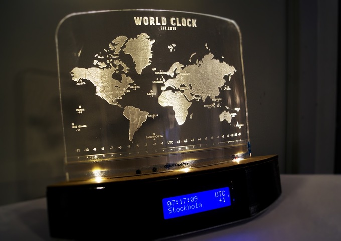
He started by designing the entire thing in CAD. The base is 3D printed on a Ultimaker. The world clock display is a piece of laser engraved acrylic which he heated up and curved to fit. Using an Arduino and a 16×2 LCD matrix he created a simple clock program with the ability to show different time zones. The way you select them is very clever.
A thin strip of brass is located at the bottom of the display, which acts as a touch-sensitive resistor strip. Depending on where you press it, the resistance changes and the Arduino switches to that timezone. It’s a clever use of an awesome sensor which really gives the project a nice touch. Not bad for a 6 week school project!
Speaking of laser cut clocks, check out this absolutely ridiculous geared pendulum clock made out of acrylic!
[via r/DIY]


Very elegant.
“Error loading this resource” for the video..
@bthy Visit the page – it’s all there.
On Topic: A very impressive build, and fancy! I love the use of the brass strip…a very stylish choice for time change (I first thought there would be a potentiometer in the base!)
I just removed the video, but as [supershwa] mentions, you can see it in the included link.
Could be fun to light only part of the map, to show the current day/night zones as they move over the globe. Though I don’t know a way to make it work for the latitudes.
Very nicely done. Hope Markus got top grades for it!
Betcha Obama doesn’t invite him to the White House for making a neat (and useful) clock.
Of course not. The racists haven’t shown up in the comments here yet.
This guy actually built a clock and Sweden can’t vote for him, so that would be a big “No”.
clock without a crystal?