In this three part video series we watch [Dirk Herrendoerfer] go from scraps to a nice 3D printed assembly as he iterates through the design of a pen plotter for making circuit boards.
[dana] mentioned [Dirk]’s work in the comments of this post which describes a different process. Many permanent markers stick to copper well enough to last through the chemical etching process. While hand drawing definitely produces some cool, organic-looking boards, for sharp lines and SMDs it gets a bit harder; to the point where it becomes advisable to just let a robot do it.
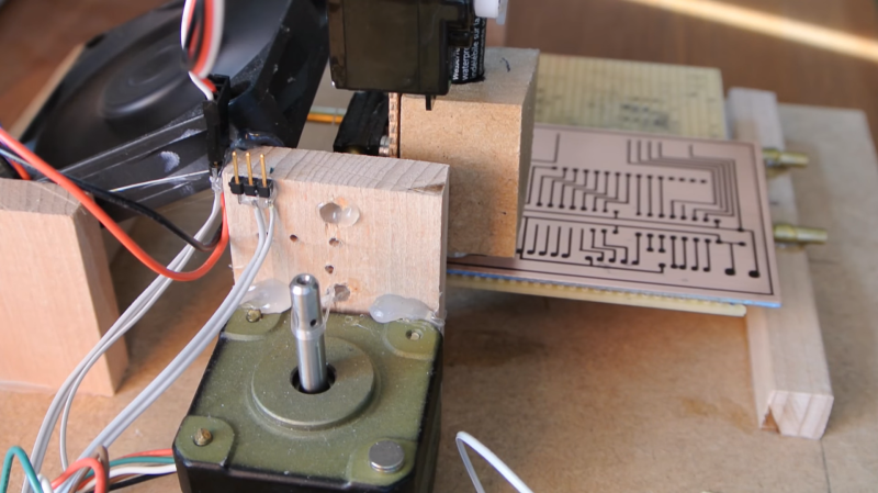
Of course, [Dirk] was aware of this fact of life. He just didn’t have a robot on hand. He did have some electronic detritus, fishing line, an Arduino, scrap wood, brass tubes, and determination. The first version‘s frame consisted of wooden blocks set on their ends with holes drilled to accept brass rods. The carriage was protoboard and hot glue. Slightly larger brass tubing served as bushings and guide. As primitive as it was the plotter performed admirably, albeit slowly.
The second version was a mechanical improvement over the first, but largely the same. The software got a nice improvement. It worked better and had some speed to it.
The latest version has some fancy software upgrades; such as acceleration. The frame has gone from random bits of shop trash to a nicely refined 3D printed assembly. Even the steppers have been changed to the popular 28BYJ-48 series. All the files, software and hardware, are available on GitHub. The three videos are viewable after the break. It’s a great example of what a good hacker can put together for practically no money.


You know what, we rig an X-Y CNC frame-emyjig with a bit of Z maybe and then what, we do 10% of the job with it… just hit me.. why aren’t we making wire wrap heads for our 3D printers, design, place pins and components in perfboard, flip it upside down sponge clamped on your rig, hit the button and it’s wiring the damn thing up, done deal when it’s finished.
https://en.wikipedia.org/wiki/Wire_wrap#Semiautomated_wire_wrap
Because wirewrap is not all that useful anymore?
Through-hole components are slowly going the way of the dodo, with many parts being available only in SMD packages. The wirewrap posts and sockets are hard to get. Perfboard for wirewrapping is hard to get. Also wirewrap utterly fails at anything remotely high frequency due to the enormous parasitic inductances of the wiring.
I understand the nostalgia for it, but … why?
You can change wire wraps with dupont, I’ve changed dupont with molex, molex with rj45 and so on… don´t blame to nostalgia with on hand stock.
The problem with this would be maintaining your nozzle head from tripping on already placed wires and components. I imagine this wouldn’t be as trivial as you might think.
“Also wirewrap utterly fails at anything remotely high frequency”
So would 95% of hobbyists board layouts and choice of PCB materials and construction. It’s like saying an arduino doesn’t run windows.
and wire wrap isn’t nearly as bad for high frequency as you might think, with a PCB that is basically a ground and power plane bypass is decent, the wires are basically as short as physically possible, matching lengths or even doing twisted pair is easy
Wirewrap is the best thing since sliced bread for fast prototyping without the expense, wait or chemicals of a PCB. Despite the fact that they’re not wirewrap pins, wirewrap works fine for patching headers on different modules together (which, with the ever falling cost of pre-built “breakout” boards from the Middle Kingdom, is what a lot of us are doing nowadays); plus it doesn’t fall off when you move your new creation six inches to the left.
I -don’t- yearn for the days of troubleshooting a wirewrap problem on a disk-drive chassis, though (a rare, but very frustrating experience) and wirewrap wire is getting to be -very- expensive nowadays, too.
[Hah! When was the last time you referred to a disk-drive “chassis”?!?]
Replace the pen with a scribe and make a cheap knockoff of a $600 Kickstarter project.
Just saying.
Anyone have a video of an automated wire wrapping machine?
Polished and precise job. I’d like to do something like yours (hopefully with the same quality !). I’ll surely take a look at your github page, well done.
Love it. Especially what looks like fishing line for the driving the print head. Schmick.
Well that’s a nice surprise !
Nicely done, [Dirk].
Thank you !
To answer some questions:
– Yes it’s fishing line.
– I use g-code as opposed to HPGL because I can plainly speak it, most other formats can be converted to g-code in some way.
– It can also do isolation scratching, just replace the felt tip of the pen with a sewing needle or use a 405nm laser with photopositive coating or spray paint.
– Yes, using a silver pen works to create simple circuits on overhead foil or plastic.
– Any etching method works, as long as it does not dissolve the ink.
Cheers !
Dirk
This is awesome, and relevant to me, because I want to make a plotter for drawing on paper : ) Curiously, why did you choose to read GCode instead of HPGL?
This project doesn’t get nearly enough love. It’s just so well done.
I wonder, is there some way to dispense acid using a marker pen like device?
For small amounts you could put a syringe in the pen-holder, and use a motor to press the plunger to dispense it. Larger amounts needing a tank of acid would have to be a tube and a peristaltic pump that forced the acid out.
If you’re thinking this could be used to deploy etching, I’m thinking maybe, but usually you want to do the whole surface at once and then wash it off. A three-minute print time probably means the first section gets etched too much, and the last section has too little acid contact time to remove the copper layer.
You could submerge the PCB into some etchant that is inactive at lower temps and use a laser to heat the sections you want etched off – no idea if that works, copper is a good heat conductor.
dherrendoerfer, I don’t think this would work, because of the refraction, using snells law to calculate the refracted angle, in perfectly still water the refracted light would come be 45 degrees, not to mention and waves that might occur
Has anyone used one of those cheap Chinese laser engraving machines to do this? You could black out the whole surface and then burn off the ink with an inverse image?
Partly, yes – but I have not been able to get my hands on one – I coated the board with Edding 3000 and was able to blast lines into it, but the lasers I have are too weak.
Firstly this is a very good project. Especially the use of the cheap steppers. The alternative to grbl is a really nice thing to find.
Secondly I have used the k40 laser cutter to burn off paint to etch.
If you are looking to make a project with low cost cnc and include servos or laser this might be a good starting point.
Well done!