In this three part video series we watch [Dirk Herrendoerfer] go from scraps to a nice 3D printed assembly as he iterates through the design of a pen plotter for making circuit boards.
[dana] mentioned [Dirk]’s work in the comments of this post which describes a different process. Many permanent markers stick to copper well enough to last through the chemical etching process. While hand drawing definitely produces some cool, organic-looking boards, for sharp lines and SMDs it gets a bit harder; to the point where it becomes advisable to just let a robot do it.
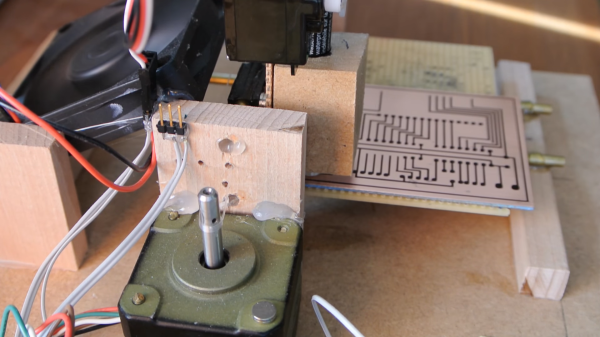
Of course, [Dirk] was aware of this fact of life. He just didn’t have a robot on hand. He did have some electronic detritus, fishing line, an Arduino, scrap wood, brass tubes, and determination. The first version‘s frame consisted of wooden blocks set on their ends with holes drilled to accept brass rods. The carriage was protoboard and hot glue. Slightly larger brass tubing served as bushings and guide. As primitive as it was the plotter performed admirably, albeit slowly.
The second version was a mechanical improvement over the first, but largely the same. The software got a nice improvement. It worked better and had some speed to it.
The latest version has some fancy software upgrades; such as acceleration. The frame has gone from random bits of shop trash to a nicely refined 3D printed assembly. Even the steppers have been changed to the popular 28BYJ-48 series. All the files, software and hardware, are available on GitHub. The three videos are viewable after the break. It’s a great example of what a good hacker can put together for practically no money.
Continue reading “The Evolution Of A DIY Circuit Board Plotter”


