[Dan Kouba’s] parents replaced their doorbell button with one that lights up and found that the chime wouldn’t stop sounding after the button was pushed. These lighted buttons use an incandescent bulb in parallel with the button (a piece of hardware we’ve hacked in the past). It draws a small amount of current which isn’t enough to trigger the chime, but it is just enough that the chime unit reacts as if the button press never stopped. His parents asked what he could do about this and after some investigation he build a replacement board for the chime unit based around an ATtiny26L. The board monitors the voltage drop across a resistor in the doorbell circuit. When the comparator on the AVR detects a rise in the voltage drop across the resistor it rings the chimes, actuating the solenoids with a set of PNP transistors. [Dan] sent us all of the details which you can check out after the break.
Dan writes:
My parents have this really old door mechanical chime that they got as a housewarming gift 25 years ago, and recently when they replaced the doorbell button with a newer lighted one, the bell wouldn’t stop chiming. Apparently the light in the button passes enough current through it while its on (and the button is unpressed) that it triggers the bell over and over again. They didn’t want to get rid of the doorbell, as the newer electronic ones just aren’t the same, so I was asked to see what I could do about it. My solution was this project.

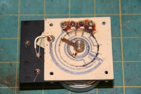
The old chime system consisted of a motor, which would be set into motion by pressing the button, and a set of contacts which the motor would revolve around and trigger the four solenoids that ring the chimes. Once I disassembled it, the cause of the infinite cycle was obvious. The motor’s start current was higher than the light in the bell would permit, but once it was triggered once by pressing the button, the bulb current was enough for it to remain in motion. There wasn’t a whole lot I could do to fix the old system, so I designed a microcontroller based replacement.

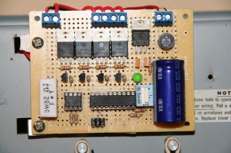
I used an Attiny26L (admittedly overkill, but it was all I had on hand) for the brains of the operation, a button press detector made out of a comparator and a resistor (more about that in a second), and four transistors for triggering the solenoids. Those parts along with the power supply (there was 20VAC available at the wall) fit onto a radioshack PCB which happened to fit perfectly where the old system had sat. The old system had the option to either chime a sequence or only a single chime when the button was pressed, and I replicated this feature in software using the large blue DIP switch shown in the pictures.
My detector circuit is simply an 82 ohm 5W resistor inline with the button/light combo. The button and the light are in parallel, so there is always some current passing through the line, causing a small voltage drop across the resistor. When the button is pressed, the light is shorted out and the current becomes much higher, thus causing a higher voltage drop across the resistor. I used a comparator attached to a voltage divider reference (half the supply) and to the resistor. That in turn is connected to the AVR which monitors for the button press and triggers the chime accordingly.

One of the problems I ran into was that the solenoids are high side switched. One lead of each solenoid is attached to the case, so unless I wanted to run 4 more wires, I had to use PNP transistors to switch them (I would have used MOSFETs, but I had the transistors in my parts box). I used an NPN transistor to pull their bases low so switching from my 5V AVR was easier.
The code is really simple; it’s just an infinite loop watching the comparator output for a trigger, and after that it triggers either the chime sequence or the single chime based on the switch input. I was originally going to use interrupts, but I had issued with multiple triggers. The interrupt flag was cleared as soon as the ISR was being processed, so if the bell was pressed twice before the chime sequence was finished, the interrupt would trigger a second time once the ISR finished its first run. A simple if…then statement fixed the problem.
Download [Dan’s] code and schematic package.


Or…even simpler….as I’ve done before…cut out the light in the button?
excellent overkill on all fronts!
Or replace, with resistor & Led?
Use a led?
Good work anyway.
Why not a relay?
El wire ring
Gotta agree with the other posters, replacing the light with an LED would have been much easier, more cost effective and more efficient. Ah well, props for the work that was done anyway. :)
I assume you programmed it to be the traditional
Ding-Dong-Dang-DUNGGGG-DUNG-Dong-Ding-Dang?
Seems feasible to reprogram that melody to something else that fit in that 4-note chord, or even sound multiple chimes at once.
with a relay, the original circuit could have been kept, just use the relay to activate it the way the button used to, but using a microcontroler allows for more fun things like playing custom songs on the doorbell
nice project:)
OMG. if it could be done on 4 chord’s, Mario theme song would be WIN… xD
Why not use the analog comparator built into the AVR?
+1 for mario theme song.
Was not a whole lot he could do? Knows very little about electronics he does….
a single relay would have solved it, but wait, let’s go further, replacing the bulb with an LED.. that would have worked very well.
Hack-a-Day Projects for N00bs that know nothing about electronics. Tomorrow, how to fix a flashlight that has the batteries in backwards! Hint: it involves rebuilding the bulb with the parts from a motorcycle!
Push doorbell button, linked to a stick, which then pokes a squirrel on a treadmill, squirrel (AKA rat on crack) turns treadmill connected to a small generator, creates current, then trips doorbell.
@fartface
I can’t resist but have a bit of a go at you – can you really tell me you wouldn’t have had a go at over complicating it just for the sake of it? I know I would, and it was fun, or at least if you don’t appreciate it you shouldn’t bother with this site really! It was a good hack, and why not overkill, he obviously has some skills, and has used them to a much larger extent!
There is no reason for sarcastic flaming, it just makes you look slightly over-obsessed and angry!
I agree that I’d have probably considered trying a relay or other means of interrupting that current path to the motor.
That is what I would have thought of . . . until I realized that I had an excuse to overkill something and make the doorbell programmable and then I would have convinced myself that the relay approach couldn’t possibly work.
“the comparator on the AVR detects a rise in the voltage drop”
What? ôo a rise in a drop? How’s that supposed to be?
Seriously killer project. for the simple fact that you could program other songs as stated above. you could even go so far as to have it automatically change the song based on holidays season, birthdays etc. Why do a simple relay when you can do what was done here. Seriosly Awesome Job!!
Humm, maybe redo for a 4 octave chime? This is starting to feel really nice.
@nomad, maybe the voltage drop is (for instance) 0.5v, and when the button is pushed, the voltage drop is 4.5v. That’s a 4.0v rise in the voltage differential (or drop).
Haters gotta hate….
Replacing the incandescent bulb with an LED would have changed the color of the button… warm white LEDs are not generally as warm as incandescents. And an LED is more efficient but it still draws current, so there is no guarantee that it would even solve the problem.
Sure, a relay would have worked, but that doesn’t mean it’s the right solution for him. Projects can be enjoyable just in the doing. And furthermore, the end result of the two is not the same. With his project he now has a programmable solid-state doorbell system. With a relay he would only have brought the original system back into working order.
Project author here…
I didn’t even think about using the on board comparator! I was originally going to do this all in logic (just because I could) so the comparator was a remnant of that idea.
This was my first true AVR project, as all my other ones were done on either a Basic Stamp or an Arduino, so there’s much I have to learn.
Thanks for all the feedback!
Wheres the rs232 or ethernet port?
voltage drop is a number. numbers can rise.
if the voltage drop goes from .5v to 2v, it has risen. It may sound strange, but it’s correct.
Think forward he is.
Now he could even tweet, flash the house’s lights, start all the alarms in the house, turn off the TV, freeze his computer, or put some bread into the toaster whenever somebody press the chime button =).
Seriously, I’m impressed how clean and neat the board ended. And well, to learn something is never overkill!! In my opinion this is how skills are developed. Simplistic, fast, practical, cheaper solutions are in the engineering area… own projects are own ideas a personal path.
I like the comments about custom tunes.
If the four notes are the same as the Westminster chimes (or if not), he could implement a real-time clock and have the doorbell sound off every quarter hour or etc.
Other audible goodies:
– alert when motion detector lights at front / rear doors go off.
– alarm clock / countdown timer / kitchen timer.
why cut out the light? Just hook it up to 110VAC until it burns out. Should not take long…
i would kinda like for my doorbell to tweet when someone rings it. then twitter could actually be semi-useful
That’s a nice map to the right in the upper image. Anyone knows what map it is?
Actually, this could be useful as a keyless door lock. A simple press of the button would ring the chimes, but pressing a special sequence could unlock an electronic deadbolt on the door. Now THAT is worthy of an Arduino!
but I had issued with
=/
but I had issues with
Sooo… Overkill ever? Lol
No one does analog circuit design anymore :(
I just moved into a house with the exact same doorbell! I’m going to have to use this and do some experimentation!