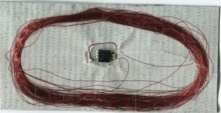
A few years ago, [Beth] came up with the idea of using an AVR as an RFID tag. She’s gotten sidetracked with a few other projects in the meantime but her idea has surfaced again, this time as a duct tape RFID tag. The build is just four components: 0.1 µF and 1 nF capacitors, an ATtiny85 microcontroller, and 100 turns of 40 AWG magnet wire, all soldered together and placed on a duct tape substrate.
Like most RFID tags, the power is drawn from the reader through the coil, but even in low power versions the ATtiny is only rated down to 1.8 Volts. Since the microcontroller is only getting about 1 Volt from the coil, the clock oscillator of the ATtiny won’t work. This isn’t a problem in this build, because the coil is connected to the the clock input – the 125 kHz coming off the reader provides the clock. Very clever.
Of course, the microcontroller is going to need some firmware to send some bits to the reader, so she used the AVRFID firmware (check out the comments in the source for a great walkthrough) to transmit under the HID protocol, itself a derivative of [Beth]’s earlier work with the EM4102 protocol.
Not only are we impressed with this hack, we’re amazed [Beth] is still perfecting her work more than two years after her first post on the subject. That’s dedication and unbridled cleverness.
Via adafruit


Thats also one long lasting RFID gaffer should keep it secure for years!
Tokenized RFID anybody?
The RFID tags that can’t be spoofed, that should be a gold mine… Or well anything can be hacked but it would make it MUCH harder if the chip didn’t send out the same signal each time.
put a cryptographic challenge/response protocol in it and you have a working and affordable security measure. Has been working for cars for a long time.
cept push to start is incredibly vulnerable to relay attacks. If you dont reprocess/decode the signal just pass it over a stronger channel then back to the original the additional time added to the loop is so small its hard to detect a relay with out introducing the possibility of false positives and people pissed their car isnt turning on.
Only 1 Volt received from the coil?
Are you sure the circuit is tuned to resonate correctly? I had a similar project up and running a few years ago and could receive 5V on the receiver coil, more than enough for powering an LED at 20mA.
My “reader” was just a 12V square wave generator being fed into a tuned load.
Never did finish the project off, but RFID is very cool to play with.
Anyone know of an ATtiny85 firmware that would work with Casi Rusco RFID tags?
RFID thermometer anyone? :-)
Ought to work, change the six end bits in the code to read temperature and Bob’s your auntie.
Wonder if you can get AVRs in a thinner package, this would work well if you laminated it.
How does the RFID signal get rectified to provide DC power?
@ bothersaidpooh:
That would be a very VERY cool (and green) alternative to traditional battery-using wireless thermometer systems like the one I use at home.
If the range is short, then I’ll just build three robots to roam around and take readings, and you know, “…take care of the forest.”
http://r.b5z.net/i/u/10046557/i/louie_drone_silent_running.jpg
http://www.youtube.com/watch?v=NkF05D-NJMU
@toybuilder
The input on the processor has interval diodes to give it some protection against electrostatic discharge. There is a diode up to the +ve rail and a diode from -ve rail up to the input. So that will cover the rectification.
I would highly recommend searching online if you want to do a similar project. There are many better sources of information and better designs out there.
internal diodes even