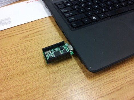
[Parker Dillmann] is nearing the end of the prototyping process for his Propeller development board. He wanted a tool that let him work on projects without the need for a bunch of equipment, while still maintaining the ability to extend the hardware when necessary. His last dev board used a large piece of protoboard to host through hole components including the Propeller chip, 3.3V and 5V regultors, an SD card reader, and female pin headers. This version migrates to a PCB from a fab house and mostly surface mount components.
He decided to use a USB-stick design having been happy with some of TI’s prototyping tools. The Parallax branded development boards use an FTDI 232RL chip for easy programming and that’s what he’s gone with as well. A P8X32A chip in the QFP package was chosen for easier soldering than the smaller QFN option. There’s also a 64kb EEPROM on board to give you plenty of room for your SPIN programs. All the pins are broken out to DIL female headers and there’s a power header on the end opposite the USB plug. [Parker] plans to do a bit of testing to make sure there’s no problems with signal routing below the 5Mhz crystal footprint. This run of prototypes came from the Seeed Studios Fusion PCB servcie–he got more than 10 boards for a total of $13… that’s almost unbelievable.


It’s alright…I guess
Thanks for the tip. I’ll be looking into their PCB service that’s a great price.
I ordered from them once and have a second order on the way. The boards were great. The customer service is a little iffy but still not bad.
Pushing down to connect something to the header connector could be a potential problem here.
Unplug it and connect hardware and plug it back in? You shouldn’t be hot plugging hardware to begin with.
Some serial ports require some sort of tickling to make them put out more than just a small amount of current. I don’t think he took this into account.
The FTDI 232RL chip takes care of all that.
I hope it comes without the female pins so that it can have male pins installed and can then mount to a breadboard, connected to a PC using a USB extension cable.
Also, gotta give props for using FreePCB…Eagle is too easy, it just feels like cheating…that is why I use FreePCB as well.
The full production board will come with either male or female headers.
Actually I find FreePCB easier to use then Eagle. I do have a background in Auto CAD so this is probably why.
Consider this a design review… just my 2 cents ;-) Please don’t take offense.
I’m hoping you used the autorouter, because I see all of the reasons why I don’t like autorouters. Many of the tracks are just too close to opposing nets, when there’s no reason for them to be. There is lots of space available to tweak the tracks away from those opposing nets.
Beef up the segments that touch through hole pads for better reworkability. This will add stability and heat sinking to your TH pads when you solder or have to desolder them. It’s free.. so there’s really no reason not to do it, unless you just don’t have the time to do it.
I like the fact that it plugs right in, but wonder how reliable and useful that will be when you are potentially cantalevering your whole design out on a USB diving board. I’ve had plenty of larger USB drives fail because of this.
Your LED polarity silkscreen is way too small to be useful.
You should TENT your vias to prevent shorts between them, especially when they are under fine pitch IC’s.
The price is right for that service!
I don’t use propeller uC’s, but thank you for open sourcing your project!
Yup the pcb has some minor problems. This is the first full SMD pcb I designed so the thought of capping vias did not cross my mind.
I have used TI’s msp430 stuff and had stuff hanging off. By the time its to heavy for the USB plug you are usually over your 500mA limit hehe.
Thanks for the review! There is a reason why this version is only going out to some people for testing before I finalize the design.