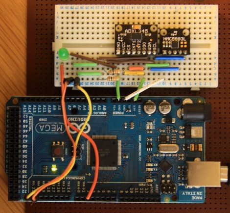
If you’re familiar with using a compass (the tool that points to magnetic north, not the one that makes circles) the concept of holding the device level makes sense. It must be level for the needle to balance and rotate freely. You just use your eyes to make sure you’re holding the thing right. Now think of a digital compass. They work by measuring the pull of a magnetic field, and have no visual method of showing whether they’re level or not. To ensure accurate readings you might use an accelerometer to compensate for a tilted magnetometer.
The process involves taking measurements from both an accelerometer and a magnetometer, then performing calculations with that data to get a true reading. Luckily the equations have been figured out for us and we don’t need to get too deep into trigonometry. You will, however, need to use sine, cosine, and arctangent in your calculations. These should be available in your programming language of choice. Arduino (used here) makes use of the avr-libc math library to perform the calculations.


If you were to use a cheap tilt compensated compass like the LSM303 you get both sensors in one package.
There is also no reason why you can’t use the two sensors independently either.
RC pan/tilt head tracker anyone?
How fortunate that this article came up! I’m beginning work on a project for exactly this, and I have a question…. Most applications are dealing with relatively static forces such as an RC pan/tilt platform which comes to mind for some reason. A motorcycle both tilts and experiences G-force (acceleration) through a corner, and I’m building such a compass for next spring. My problem is that the gauges have too strong a field to mount a typical magnet compass anywhere near the gauges, hence it would not be within sight if placed where it works. So I have to place the magnetometer/accelerometer remotely and put only a display at the gauges. I have NOT gone through the math in detail as yet as I’m still selecting components, but the question does arise that cornering G-force may or may not be compensated for by the accelerometer. At face value it seems it will be, but then again as applied it seems the accelerometer is only measuring direction of gravity (tilt) and G-forces add a whole new complexity that may require speedometer input to compensate for.
Opinions? Any lucid experts on the subject?
Sounds to me like its going to take adding a rate gyro to note the cycle’s change in direction and use that to correct the accelerometer output to establish a correction factor and derive the actual tilt of the system for the compass. Then again I note that a magnet compass is “upset” during a corner and gives unusable readings till you settle out to level and straight. This means that for my application use of an accelerometer overcomplicates things and adds a rate gyro to compensate, when a plain old magnet compass has problems during the very same turn. Hence, best bet would be to just use a plain 2 or 3 axist magnetometer to get the same accuracy as a magnet compass and accept that it’s valid only during straight line travel.
… or just buy a gyro compass
Yes, ’cause and aligning a gyro is way better.
Somebody has to add, that accelerometers can’t distinguish tilt from acceleration. So if acceleration may be present, you need to add rate-sensors (gyros) and use them for the calculations. …my 2 cents.
And then BAM! Kalman filter.
You just made my day ;)
Did you read the article itself?
There is a very good explanation covering this point and the next stage of the project will be to add the gyro.
@JohnnyMax
I must admit that I did not read the article before posting my comment…
Best wishes to loveelectronics to get it right : the AHRS algorithm in standard Arduino programming will be a really nice thing.
Just out of curiosity: Is the magnetic declination compensated in the magnetometer? Does anybody know?
http://en.wikipedia.org/wiki/Magnetic_declination
Bernt Weber,
DIY Drones has produced an Arduino based AHRS using a “DCM”(Direction Cosine Matrix) algorithm as an alternative to a Kalman Filter. Download the ArduIMU code and it should be included as a library.
“Matrix Pilot” is another project with really good open source code. Matrix Pilot uses the Sparkfun UAV Devboard I believe.
On a final thought, Kalman Filter is an included functionality of OpenCV which now is fully compatible with “Android”.
You may decide to kill 2 birds with one stone and use an IOIO + Android as your Display and handle the DSP algorithms(kalman) with your phone.
Magnetic declination compensation requires knowing your position on the globe and looking up the declination correction factor on a reference map. It is not not compensated for in the magnetometer. It would require GPS and a lookup table.
Thanks, for your explanation!
Being someone who has used trig functions on both AVR and arduino, they introduce a rather large error due to rounding in the math library. To do this more accurately, you need a lookup table, math co-processor, or a 32bit platform, imho.
The magnetic declination issue is discussed in their earlier compass tutorial before tilt compensation: https://www.loveelectronics.co.uk/Tutorials/8/hmc5883l-tutorial-and-arduino-library