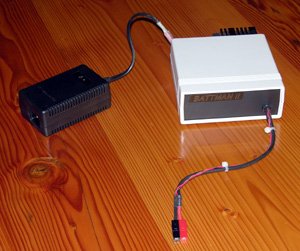
When your radio controlled device batteries are drained, you’ve got no better option than to call on BattMan II. This device is packed full of features for cycling and charging various types of batteries. It is computer controlled via your parallel port (yeah, remember those?) and has companion software that allows you all kinds of control and data.
The writeup is rather extensive and includes schematics so you could build your own. There’s also a step by step breakdown of how each section functions as well as an explanation of each different charging method. Great work [Stefan]
if you just want a peak at the lengthy feature list, keep reading.
The hardware feature list:
- Works with Nickel-Cadmium (NiCd), Nickel-Metal-Hydride (NiMH), Lithium-Ion (Li-Ion), Lithium-Polymer (LiPo), Lithium-Nano-Phosphate (LiNP), and Lead-Acid (Pb-Acid) batteries of 1.2 to 14.7 Volts.†
- Discharges batteries to measure capacity at rates of 130mA to 2A.
- Charges at rates of 130mA to 1.3A.†
- Automatically performs repeated discharge/charge cycles to break in new batteries, or erase NiCd voltage depression in old ones.
- Measures internal resistance.
- Monitors self-discharge.
- Real time graphical display lets you see problems like mismatched cells.
- Keeps a log of all operations performed, which can be imported into any spreadsheet program.
- Saves graphs of charge, discharge, auto-cycle, and monitor operations.
- Connects via parallel port to any PC running Microsoft Windows (95, 98, ME, 2000, XP, Vista, or Windows 7).††
- Operating software, complete with source code, is available to download.


This is a great device, Especially as devices that measure the capacity of batteries are normally £100-£200!
I would pay for something professional like this, although it would need a failsafe!
A well-done project! Too bad it requires a parallel port; they’ve gotten pretty scarce on modern PCs.
Are there any USB-to-parallel adapters that would work with your present software? All the ones I know of are poor emulations of a PC parallel port.
I agree that a failsafe circuit is virtually mandatory on a project like this. A runaway charger on a lithium cell can start a fire!
No MCU. Requires a computer, and interfaces to it through a parallel port. Linear current regulation. How retro!
Yet I *really* liked looking at this. Everything is done with class. The circuit is simple and elegant, but packs a lot of versatility. The documentation and color-coded schematic are top-notch. Most importantly, it looks like it’s a great battery charger and conditioner.
For me it also evokes nostalgia, because it reminds me of my first major electronics project; which was similarly interfaced via parallel port and Borland C.
Definitely worth learning from, or even building.
This is a classic circuit that still works great today. It would be pretty simple to add a uC on the parallel port lines and do the comms over USB if you don’t have a parallel port.
I too love the thought that went into the schematic with color coded blocks. A great example for how to present an electronics project that is easy to understand and build!
did somebody say teensy++?
this charger looks great ive been thinking about making something to charge NiMH 3.7 volt batteries ex: laptop and mp3 cells, and i’m kinda partial to the teensy also.
Thanks for the comments everyone. I hear you about the parallel port! Problem is that when I built BattMan I, there was no such thing as a USB port, and when I built BattMan II, I just stuck with what I knew.
I’m not aware of any parallel-to-USB adapters that will work, since they just make the port appear as a USB printer to the computer, not an actual parallel port with bits you can twiddle.
I also agree about the failsafe. I have a few designs, some of which I came up with, and some of which were submitted by readers. I need to pick one and add it to the article.
Thanks for the comments everyone. I hear you about the parallel port. Thing is, when I built BattMan, the only choices were the parallel port or an RS-232 serial port. So when I designed BattMan II, I stayed with what I knew (and my workshop PC had a parallel port).
None of the USB-to-parallel adapters out there are likely to work. These just look like a USB printer from the computer side, not an actual parallel ports with bits you can twiddle.
I have several designs for a fail-safe, some of which were submitted by readers, and others I designed myself. I need to pick one, implement it, and add the instructions to the article.
Having just finished the project I will vouch that it truly is a great device to have. Total cost is about $35-$40 shipped from mouser plus wire, permanent markers, and PCB etch. Most lithium capable chargers will run at least $60 (granted they can balance as well) but they certainly wont give you this much information on the performance/health of your battery and they definitely won’t PROVE that they are actually working like this does with the data logging. Nor are they such an interesting project.
I think the software on the computer side is well done and it shouldn’t be so hard to give this USB connection.
Just use some micro with usb + ADC (say ATMEGA32u4) and the circuit will be much simplified. PWM filtering will also give the DAC functionality.
Failsafe will also be easy to use in the microcontroller.
impressive.
clever how instead of measuring analog, you create and then compare analoge :)
would go well in a lab alongside a “DB-25 AorB selector”
a very good read
insert my trademark REmarks about how a parallel port can be easily made from two logic chips and a IDE/PATA port …
I built this in Jan of this year and have to say it’s already paid for itself. I made a few changes to the plans that were available then. Mostly to the fan circuit and heat sink. But it was my first full blown project into making etched boards. Which I’ve gone much further with since. SMD’s YEAH!
For me a dedicated PC with parallel port is no issue. I’m using a ATOM mounted on the back of my monitor and it runs well along with the home automation software it hosts.
Thanks for reminding me about this great project! I’m going to look it over and see if it’s updated from when I built it and do the same.
Great job on the PCB layout!