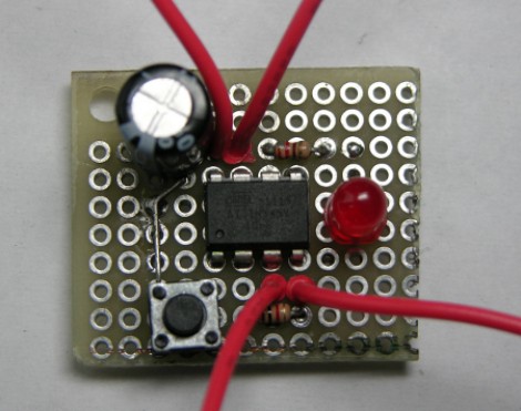
As is common among some hackers, [Henry] re-purposed an ATX power supply unit to function as a bench power supply for testing circuits on a breadboard (much like this fancy example).
However, safety mechanisms on some modern PC PSUs do not automatically reset after over-current protection has kicked in, which soon became annoying for [Henry]. In order to make his power supply more hacker-friendly, he wired up and programmed an ATtiny85V, using some Arduino libraries, to do that for him. This simple project is a great example of using a hack to improve a pre-existing hack.


Reblogged this on txwikinger's blog.
A single 8DIP, a capacitor, and two resistors? I wonder what other chip he could have used to do this for him…
A PIC12F629?
Sorry, I had to :)
555 timers really can do just about anything!
Wait, could it be? Arduino wallpaper on the linked site by the looks of it. Thanks Hack-a-Day :)
any time decker :)
may be possible to change out a shunt resistor used to detect the load with a value that would make a dead short required to trip it .
only problem is some of the chips in the power supply may be proprietary or the detection is done internally and not through a pin.
it is like the record stopper on a video dvd recorder that detects the macrovision signal is built into the cpu chip and not a separate detector that can be disabled.
i had a computer powersupply once that did NOT have ANY overload protection…
hehehe
safe to say it needed unplugging… ;)
could have sued if it werent for my shorting it on purpose,
but if it had shorted by accident while sleeping…
i would NOT have been quick (edit: awake) enough to unplug it.
PS: fuse was ditto: 6A @ 120v = ~700W on a 200w supply. YIKES!
THIS IS ALLOWED FOR SALE IN A “1ST WORLD” COUNTRY!?!?!?!?!?!?!
WHERE IS THE UL OR CSA(europe:TUV)????
USELESS SORRY EXCUSES FOR A “safety testing”
yeh, nice safety test a******s
by “needed unplugging” i meant the wires started smoking and glowing red-hot (actually hotter; orange)
a busted mother board can provide the connector. you can desolder it by heating a small aluminum plate on a electric burner then holding the edge of the motherboard that is under the connector on that until you can work the connector free.
I find using a heat gun and then either lifing the connector off or…when hot giving the board a solid whack on the ground (solder side facing down) will also dislodge most if not all the solder and causing the connector bounce upwards. This method also dislodges any near by loose components thereby minimising heat stress in the process. I do strongly recommend wearing suitable safety gear.
dont you guys know about a desoldering iron?
i use mine to nudify basically any throughhole component on any pcb.
p.s. i love all the capacitors and jacks motherboards have.
Hi Jacob,
I’m commenting on your latest post in an effort to get a hold of you. I am looking for the files related to this project: http://hackaday.com/2009/10/03/garage-door-packet-sniffer/
. I would appreciate it! Thanks!
Hey everyone, here is a tidy version fo the shcematic I made in eagle cad:
http://i988.photobucket.com/albums/af1/XOIIO/Eagle%20Cad/screenshot3.jpg
And here is the board with as idea spacing and traces as I could make, note that the top layer trace is meant to be a jumper.
http://i988.photobucket.com/albums/af1/XOIIO/Eagle%20Cad/screenshot4.jpg