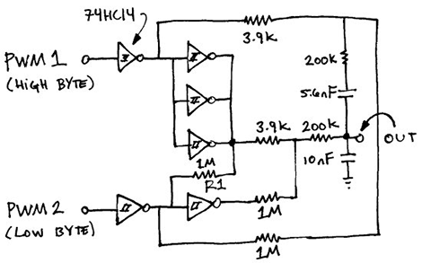
Although it’s technically possible to get 16 bits of resolution on a ATMega328, most implementations of PWM on everyone’s favorite ‘mega – including just about every Arduino sketch – are limited to 8 bit PWM. This means the pins can only output 256 different values, so if you’re playing around with music made on an Arduino don’t expect very high fidelity.
There is a clever way around this: use two PWMs, and use one pin for high bytes and another for low bytes. That’s what Open Music Labs did when working on a synthesizer project that needed very high quality audio.
The basic idea behind the build is that PWM pins can be used to create audio frequencies. Using two PWM pins and adding them together means it’s possible to add extra bits of resolution. This requires using different values of resistors on each pin. For example, using the same value of resistors on two PWM pins increases the resolution by one bit. Two pins with a resistor value ratio of 1:4 increases the resolution by four bits, and so on.
There’s a great tutorial for setting up these higher resolution, dual PWM outputs on an ATMega or Arduino, as well as a distortion analysis for this dual PWM setup.


The article is very good as theory explanation.
I’ve tried this once, going for an expansio to 12 bits. I’ve found the sound of a R2R rrsisot dac with 10bits resolution better than the 12b pwm generated.
In then end i decided to go for a low cost audio dac with a serial interface, like the CS4344 for less than 2 eur. There are others and its easiyer to solder an 8 pin ic compared to what it take to build the dac out of more pwm channels. Its probably also cheaper.
But, if 8bit pwm is sifficoent, theres no easier way.
That’s clever but when I need custom made PWMs, I prefer to code them myself.
It’s not difficult at all and you learn how to use Timers and Interrupts (every micro has a 16 bits timer in it today).
Dont forget tha a 16bit timer used with a 20MHz clock will get you 300Hz max frequency. This leaves you bandwith inusable for audio.
This is the advantage of having 2 8bit pwm, the each can run at higher frequency.
Only if you start the timer at 0 and wait for it to fill up and overflow.
In every micro I’ve seen you can load the timer with any value you want whenever you want. Load that 16-bit timer with 65,535 (and reload that value in your ISR) and it’ll overflow with every clock tick.
Of course your ISR will take some time to run, but ~305 Hz is most assuredly *not* the upper frequency limit with a 20 MHz clock and 16-bit timer.
But how would you get 16 bit PWM resolution that way ?
If you want to have 2^16 discrete PWM steps, this means a maximum frequency of 20M/2^16. If you limit what you fill with to a number lower than 2^16, you are reducing the bits of precision. If you preload the counter with 61440, you have 4096 discrete values, and can operate up to 4.9kHz but you only get 12 bits of precision….
305Hz *IS* the limit if you want 16 bits of dynamic range on your DAC for what Bogdan is talking about.
Oh, my bad, I thought Bogdan was talking about using the timer to trigger an interrupt that computes the next audio output. You all are of course right about using the timer to do the actual PWM.
Any idea why this uses 3 inverters in parallel to drive a high impedance load?
It says in the article. The output resistance of the inverter is inconsistent, so it affects the accuracy of the 1:256 ratio. To minimieze the effect they use 3 inverters in parallel to mimimize what adds to the 3.9k
Audio clip or it didn’t happen.
But seriously…audio clip? :)
There is a public library for ‘Arduino’ called SimpleSDAudio…. that can use or two pwm pins (9/10) for 16bit audio..
http://arduino.cc/forum/index.php/topic,112745.0.html
lib: http://hackerspace-ffm.de/wiki/index.php?title=SimpleSDAudio
standalone is very low quality volume and static.. but does ‘work’… (this is the minimum, pin9 only approach)….
Public library (easy to use) posted on Arduino.cc
Called SimpleSDAudio
http://arduino.cc/forum/index.php/topic,112745.0.html
&
http://www.openmusiclabs.com/learning/digital/pwm-dac/dual-pwm-circuits/
EXACTLY. WHAT. I. NEEDED. TODAY! I will totally be genning this into an attiny85! PLL’d high speed timer FTW! I can’t wait to see if it works well at 16-bits.
This is a very neat hack! I was already pretty satisfied with the audio coming out of the Attiny85’s high speed PWM (8 bits at 250khz). I’m very interested to see how much this can be improved using this technique. I’m not too crazy about throwing an inverter IC into the mix, because I’d just as simply add a cheap DAC IC. But still very cool !
Charles read Bogdan’s comment above regarding 16-bits, it won’t work out.
I didn’t get that at all.
Why do you need this masohism, when there’s a timer/counter 1 capable of delivering 16-bit PWM for 2 OC pins? Or is the datasheet for atmega328 a lie?
Whats the max frequency that you can operate the 16bit timer at?
Thanks, just remembered that we’re kind of NOT that fast on avr.
Still, you can set the top value to limit it at about 11-12 bit. That will still give reasonable quality.
For anything better – a cheap STM32F1X with 8k flash looks like a better solution with cheaper BOM and fewer external components.
Just use a 24bit serial DAC and call it done.
http://www.edn.com/file/15421-93004di.pdf
This is the original idea “I guess” that appeared back in 2004.
Interesting read and I have all of the parts sitting around to mess with it tonight. Will probably even learn a thing or two trying to get things right :) Thanks to all.