High-Resolution MIDI Controller

For an older standard, MIDI has remarkable staying power in the music industry. It remains the de facto digital interface between computers and instruments thanks to its open nature, but its age does show a little bit. Sending control change (CC) messages, for example, was originally designed to fit within seven bits, which doesn’t give particularly fine resolution compared to more capable modern computers. To work around that, a fourteen-bit message is possible, doubling the resolution, and this MIDI interface uses this larger amount of data to send these high-resolution CC messages.

The 14-bit messages are actually fairly well documented but are a bit obscure, with very limited hardware support. To that end, [Gero] set about building this control interface to solve that problem. It’s made up of only eight knobs, each of which is mapped one-to-one to a parameter on the computer, allowing the interface to feel more like an analog device where the knob corresponds directly to a change in an aspect of the sound. The platform is built around a Teensy 4.0 and some multiplexers to handle all of the knobs, with the open source software available for anyone to use to modify their actions. [Gero] was aiming for high fidelity for all aspects of this controller, not just the improved digital resolution, and made a number of other improvements to it as well like re-greasing the potentiometer knobs and a custom 3D printed enclosure.

All of the software is available for use, as well as the files to print the case. [Gero] is also working on a PCB to make the construction of the device a little more streamlined, but for now, it requires a bit of soldering off-the-shelf parts together. The MIDI standard is open as well, which allows for a lot of innovation in the creation of musical instruments from unique hardware. This project builds a MIDI synthesizer with parts from a Sega Genesis.

MRI Resolution Progresses From Millimeters To Microns

Neuroscientists have been mapping and recreating the nervous systems and brains of various animals since the microscope was invented, and have even been able to map out entire brain structures thanks to other imaging techniques with perhaps the most famous example being the 302-neuron brain of a roundworm. Studies like these advanced neuroscience considerably but even better imaging technology is needed to study more advanced neural structures like those found in a mouse or human, and this advanced MRI machine may be just the thing to help gain better understandings of these structures.

A research team led by Duke University developed this new MRI technology using an incredibly powerful 9.4 Tesla magnet and specialized gradient coils, leading to an image resolution an impressive six orders of magnitude higher than a typical MRI. The voxels in the image measure at only 5 microns compared to the millimeter-level resolution available on modern MRI machines, which can reveal microscopic details within brain tissues that were previously unattainable. This breakthrough in MRI resolution has the potential to significantly advance understanding of the neural networks found in humans by first studying neural structures in mice at this unprecedented detail.

The researchers are hopeful that this higher-powered MRI microscope will lead to new insights and translate directly into advancements healthcare, and presuming that it can be replicated, used on humans safely, and becomes affordable, we would expect it to find its way into medical centers as soon as possible. Not only that, but research into neuroscience has plenty of applications outside of healthcare too, like the aforementioned 302-neuron brain of the Caenorhabditis elegans roundworm which has been put to work in various robotics platforms to great effect.

Continue reading “MRI Resolution Progresses From Millimeters To Microns”

DVD Drives Turned Into Microscopes

With the advent of streaming services, plenty of people are opting to forego the collection of physical media. In turn, there are now a lot of optical drives sitting unused in parts bins and old computers. If you’d like something useful to do with this now-obsolete technology, you can have a try at turning one into a laser microscope.

This build requires two DVD pickups. By scanning once horizontally and once vertically and measuring the returning light from the DVD laser, an image can be created. For this build, the second pickup is used to move the object itself. The entire device is controlled by an Analog Discovery 2, although this principle could be ported to other microcontroller platforms. Thanks to the extremely fine laser in a DVD and the precise movements of the motors found in the control machinery, the images obtained using this method have the potential to be more detailed than comparable visible light microscopes.

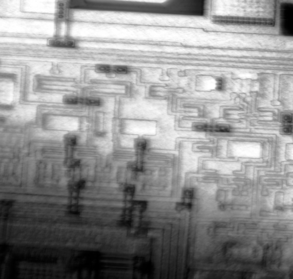
While this isn’t quite scanning electron microscope territory, it’s good enough to clearly image the internal workings of a de-capped integrated circuit. Something like this could be indispensable for reverse-engineering ICs or troubleshooting other comparably small electronics, with resolutions higher than can typically be obtained with visible light microscopes. We’ve even seen similar builds in the past which build microscopes like this as dedicated lab equipment.

Label Your Shtuff!

Joshua Vasquez wrote a piece a couple of weeks ago about how his open source machine benefits greatly from having part numbers integrated into all of the 3D printed parts. It lets people talk exactly about which widget, and which revision of that widget, they have in front of them.

Along the way, he mentions that it’s also a good idea to have labels as an integrated part of the machine anywhere you have signals or connectors. That way, you never have to ask yourself which side is positive, or how many volts this port is specced for. It’s the “knowledge in the head” versus “knowledge in the world” distinction — if you have to remember it, you’ll forget it, but if it’s printed on the very item, you’ll just read it.

I mention this because I was beaten twice in the last week by this phenomenon, once by my own hand costing an hour’s extra work, and once by the hand of others, releasing the magic smoke and sending me crawling back to eBay.

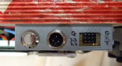
The first case is a 3D-printed data and power port, mounted on the underside of a converted hoverboard-transporter thing that I put together for last year’s Chaos Communication Congress. I was actually pretty proud of the design, until I wanted to reflash the firmware a year later.

I knew that I had broken out not just the serial lines and power rails (labelled!) but also the STM32 SWD programming headers and I2C. I vaguely remember having a mnemonic that explained how TX and RX were related to SCK and SDA, but I can’t remember it for the life of me. And the wires snake up under a heatsink where I can’t even trace them out to the chip. “Knowledge in the world”? I failed that, so I spent an hour looking for my build notes. (At least I had them.)

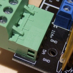
Then the smoke came out of an Arduino Mega that I was using with a RAMPS 1.4 board to drive a hot-wire cutting CNC machine. I’ve been playing around with this for a month now, and it was gratifying to see it all up and running, until something smelled funny, and took out a wall-wart power supply in addition to the Mega.

All of the parts on the RAMPS board are good to 36 V or so, so it shouldn’t have been a problem, and the power input is only labelled “5 A” and “GND”, so you’d figure it wasn’t voltage-sensitive and 18 V would be just fine. Of course, you can read online the tales of woe as people smoke their Mega boards, which have a voltage regulator that’s only good to 12 V and is powered for some reason through the RAMPS board even though it’s connected via USB to a computer. To be honest, if the power input were labelled 12 V, I still might have chanced it with 18 V, but at least I would have only myself to blame.

Part numbers are a great idea, and I’ll put that on my list of New Year’s resolutions for 2021. But better labels, on the device in question, for any connections, isn’t even going to wait the couple weeks until January. I’m changing that right now.

Portable MRI Machine Comes To The Patient

To say that the process of installing a magnetic resonance imager in a hospital is a complex task is a serious understatement. Once the approval of regulators is obtained, a process that could take years, architects and engineers have to figure out where the massive machine can be installed. An MRI suite requires a sizable electrical service to be installed, reinforced floors to handle the massive weight of the magnet, and special shielding in the walls and ceiling. And once the millions have been spent and the whole thing is up and running, there are ongoing safety concerns when working around a gigantic magnet that can suck ferromagnetic objects into it at any time.

MRI studies can reveal details of diseases and injuries that no other imaging modality can match, which justifies the massive capital investments hospitals make to obtain them. But what if MRI scanners could be miniaturized? Is there something inherent in the technology that makes them so massive and so expensive that many institutions are priced out of the market? Or has technology advanced far enough that a truly portable MRI?

It turns out that yes, an inexpensive MRI scanner is not only possible, but can be made portable enough to wheel into a patient care room. It’s not without compromise, but such a device could make a huge impact on diagnostic medicine and extend MRI technologies into places far beyond the traditional hospital setting.

Continue reading “Portable MRI Machine Comes To The Patient”

Raspberry Pi 4 HDMI Is Jamming Its Own WiFi

Making upgrades to a popular product line might sound like a good idea, but adding bigger/better/faster parts to an existing product can cause unforeseen problems. For example, dropping a more powerful engine in an existing car platform might seem to work at first until people start reporting that the increased torque is bending the frame. In the Raspberry Pi world, it seems that the “upgraded engine” in the Pi 4 is causing the WiFi to stop working under specific circumstances.

[Enrico Zini] noticed this issue and attempted to reproduce exactly what was causing the WiFi to drop out, and after testing various Pi 4 boards, power supplies, operating system version, and a plethora of other variables, the cause was isolated to the screen resolution. Apparently at the 2560×1440 setting using HDMI, the WiFi drops out. While you could think that an SoC might not be able to handle a high resolution, WiFi, and everything else this tiny computer has to do at once. But the actual cause seems to be a little more interesting than a simple system resources issue.

[Mike Walters] on a Twitter post about this issue probed around with a HackRF and discovered a radio frequency issue. It turns out that at this screen resolution, the Pi 4 emits some RF noise which is exactly in the range of WiFi channel 1. It seems that the Pi 4 is acting as a WiFi jammer on itself.

This story is pretty new, so hopefully the Raspberry Pi Foundation is aware of the issue and working on a correction. For now, though, it might be best to run a slightly lower resolution if you’re encountering this problem.

Back To Video Basics With An ESP32 VGA Display

In a world where standards come and go with alarming speed, there’s something comforting about VGA. It’s the least common denominator of video standards, and seeing that chunky DB15 connector on the back of a computer means that no matter what, you’ll be able to get something from it, if you can just find a VGA cable in your junk bin.

But that’s the PC world; what about microcontrollers? Can you coax VGA video from them? Yes, you can, with an ESP32, a handful of resistors, and a little bit of clever programming. At least that’s what [bitluni] has managed to do in his continuing quest to push the ESP32 to output all the signals. For this project, [bitluni] needed to generate three separate signals – red, green, and blue – but with only two DACs on board, he had to try something else. He built external DACs the old way using R/2R voltage divider networks and addressed them with the I2S bus in LCD mode. He needed to make some compromises to fit the three color signals and the horizontal and vertical sync pulses into the 24 available bits, and there were a few false starts, but the video below shows that he was able to produce a 320×240 signal, and eventually goosed that up to a non-native 460×480.

It’s a pretty impressive hack, and we learned a lot about both the ESP32 and the VGA standard by watching the video. He’s previously used the ESP32 to build an AM radio station and to output composite PAL video, and even turned his oscilloscope into a vector display with it. They’re all great learning projects too.

Continue reading “Back To Video Basics With An ESP32 VGA Display”