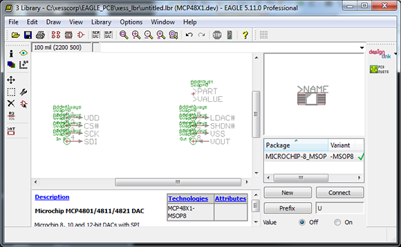
Cadsoft’s Eagle is a great tool for the independent maker. It’s a relatively easy to use PCB layout program with a ton of part libraries available for just about any project. If you’re using a part this isn’t included in these libraries, though, creating them by hand is a pain. [Dave] sent in a project he’s been working on that makes parts for Eagle with a Perl script, allowing for easy creation of custom parts that aren’t included in any library.
One thing that’s really convenient for custom Eagle parts is that most components are DIPs or some sort of leaded SMD component. [Dave]’s script takes the dimensional data from any chip’s datasheet and creates a custom outline for each part. The inputs and outputs can also be ripped directly from the datasheet and assigned to the footprint, making for a relatively automated process that creates custom parts in Eagle. Now for someone to use this script with a little OCR to make a ‘create Eagle part from PDF’ app…


why don’t we start a database of ic-footprints and pin-names that is not bound to a application.
you can define your parts with a little gui in your browser, or by a ini-style like syntax. you can fork existing parts, or add a smd variant of a existing dip part by just moving around some pins. all parts have a wiki like history and you can mark them as correct or wrong.
when your done, you click export and you will get your footprints for kicad, eagle, fritzing, or you write your own converter and just download the definition file,..
http://xkcd.com/927/
I heard back in the ’80’s…
The great thing about standards, is there are so many to choose from.
See here:
http://www.circuits.io/
It’s an online design tool They have an Octopart-powered component builder and you can fork projects (and footprints IIRC).
KiCad doesnt strictly tie footprints to parts, so you can easily re-use any DIP footprint for any new part
Just like EAGLE and most other PCB CAD packages.
Nice job but it looks like the usual unintelligible crap that Eagle produces. Can you make it legible? Or is that just how Eagle presents labels etc?
Are you talking about all the green text around the pins on the schematic symbol? That lists the swap level and other properties of each pin. The display of that stuff can be turned off.
Yeah, and it’s only shown when you’re editing the symbols anyway. Not a big deal.. just sounds like someone griping about a program they don’t use.
You wouldn’t actually need OCR – most manufacturer datasheets are text, not scanned images.
I actually tried that with some Microchip datasheets a few years ago. They were protected so you couldn’t extract their text. Since I wanted to make a complete Microchip library, I lost interest after that.
Getting rid of restrictions on PDFs is really easy if you have viewing permissions (the text has to be decrypted in the first place!). For instance:
http://superuser.com/questions/367184/pdf-removing-usage-restrictions
Seems to me there is already a ULP script that does a lot of this… Oh yeah, make-symbol-device-package-bsdl.ulp.
make-symbol-device-package-bsdl.ulp is great for doing a one-off part. But sometimes I need to modify a part. Does this ULP provide any way to recall all the information I typed into it previously so I can make just a small modification? Does the ULP have a way to make several package variants and then link them all to the same schematic symbol? If I have a library of parts and decide to make a global change to them, is there some way to run the ULP in a batch mode and regenerate the entire library without a bunch of manual point-and-click? That’s what I was trying to avoid with my perl library.
Different tools solve different problems.
I use a short perl script to convert a flat text file to a bunch of xml. The text file has two columns: pin number and pin name. I copy the xml output directly in the parts library using a text editor, and then I open it up in Eagle to rearrange the pins and draw an outline.
If the manufacturer cooperates, the pin numbers/names can be extracted from the datasheet.
After the painful switch to KiCAD I don’t have to worry about this crap anymore.
Farnell already do this for popular IC’s not already in EAGLE, they must have some guy punching out EAGLE scripts, admittedly they are crap! but a few tweaks compared to starting from scratch saves more time.
>If you’re using a part this isn’t included in these libraries, though, creating them by hand is a pain.
Not at all.
Creating a new part is a walk in the park. It wont be for the new user of course, but it is really easy.
Read the manual and/or follow a tutorial and make a few devices as a test. It’s super simple.
And, you’ll be able to make ANYTHING, not just the devices that this script supports.
I’d say that the packages supported by the script, are to 95% already in the standard EAGLE libraries. The pin-outs are not, obviously.
Scripts like this reminds of the “Give the starving man a fish and he’ll have food for a day, teach him to fish and he’ll have food for life”.
The site doesn’t work anymore. I’m making homework for a vocational training school and need to make a custom part for Vishay SOMC160347K0GRZ. It’s a SOIC-16 resistor array.
I did this quick & dirty try, but I need to do it in Eagle :/
https://123d.circuits.io/components/852060-vishay-somc160347k0grz
I asked in EEvBlog too…
http://www.eevblog.com/forum/eagle/please-help-me-making-a-custom-part-library-(soic-16-resistor-array)/msg688390/#msg688390