There’s no substitute for a proper oscilloscope on your electronics bench. But unfortunately we still don’t have one of our own. But we’ve got an Arduino board and paired with another IC it can sample an astonishing 5 million cycles per second.
[Bob Davis] has been working on an Arduino based oscillscope for a while now. He keep squeezing more and more performance out of it. A previous version hit 3 megasamples using an AD775 chip. When he added a FIFO buffer chip he was able to squeeze 10-25 megasamples out of it… wow! Unfortunately the output tended to be glitchy.
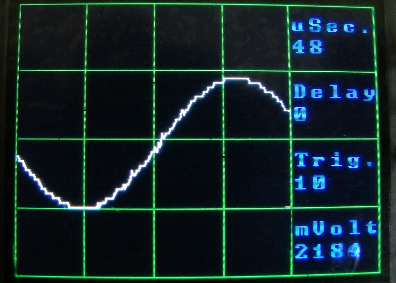
This version gets rid of the AD775 in favor of a CA3306. Both are analog-to-digital converters but the new circuit is less complex and more reliable. It uses just three capacitors and an external clock to support the IC. Take a look at the video below to see how it performs. He’s outputting a graph of the samples on a small LCD screen. The best part is that since the extra chip is doing the sampling this can be ported to your microcontroller of choice.


not quite as good as an all tube tektronics scope of sixty years ago.
I just picked up a Tektronix 2246 at an estate sale for $60. Not a tube scope, but its an amazing analog scope!
That’s still a tube scope then, CRT = tube, and that doesn’t look like an LCD display.
I picked up a Tek 453 for free. :) Not a tube scope (well, except for the CRT and the Nuvistors), and not precisely dual-trace (but is dual channel), and it’s kind of big. The build quality is astounding.
But it’s also a pretty awesome, 50MHz scope.
Just having it around for a few weeks has already let me think about things differently: I get to see what I’m doing, instead of guessing at it, trying to fool a slow DVM into being useful, or assuming that the theory is correct. And it’s so absolutely real-time that it’s kind of sickening.
Don’t know how I ever got by without it.
Hmmm, wait a second… An Xprotolab does 2MSPS at a bandwidth of 200kHz. How are you only getting 20kHz at 5MSPS?
Technically, he could do 2,5MHz with 5MSPS before he violates the shannon-Nyquist theorem. But having more samples on the same bandwidth means one has more supporting points to draw the waveform.
Here we will get a nice smooth waveform with many supporting points. The Xprotolab is a commercial product. While it CAN do 200kHz at 2MSPS, it certainly won’t do it well. It’s marketing blabla…
I need a better function generator to produce sine waves over 20 KC
The circuit is incomplete – how is the CA3306 clocked?
Could it do more if Arduino would run at 20MHz?
Any 4 MC to 15 MC clock will do. It might be possible to use the Arduino 16 MC Clock.
how can it be done?
@Eatith Mee I know, right? I just picked up a Tek 2225 50MHz scope off eBay for $75. (I even picked it up locally!) You can even find 10~ year old digital CRO’s for less than that if you look hard enough.
I mean, don’t get me wrong, I own an Xprotolab because it’s nice for quick breadboarding, but I’d never use it as my main scope… I feel the same way about these USB based scopes as well. Just get a real one! You can buy 100MHz Rigol scope brand new for $400! Or something old off eBay for $50 or less!
I wonder how he is synchronizing the conversion in the CA3306 with the data sampling routine in the arduino. I don’t see any association between the clock and reading the parallel port input which is what the ADC spec requires. Also the sampling speed must have been empirically determined based on how fast the compiled code ran (and what mode it’s in).
An interesting aside, I was just reading about the new generation of 60-70 GHz digital sampling scopes from Agilent, Tek and Lecroy. They are using multiple ADCs, each running at something like 20 GHz with phased sample-and-hold circuits and 200+ GHz cut-off frequency transistors in the front-end circuitry for each ADC. These scopes also have ungodly amounts of RAM and CPU processing power.
No synchronizing of the clock, thus the glitches. However if I tapped into the Arduino clock it might just work better. However teh CA3306 is only rated to 15MC.
Gotcha. The HaD write-up mentioned that a previous experiment (unsuccessfully) used a FIFO. This seems like a great application for a FIFO (or dual-port SRAM). A few external parts and you could easily capture data at the maximum sample-rate of the CA3306. Using the 3x sample rate rule-of-thumb, you could create a 5 MHz front-end to an arduino display back-end. In any event, I’m with the group that says that projects like this are worthwhile if you got something out of them.
My FIFO setup was successful, but then how do you slow it down via software. Not using a FIFO allows you to select any speed in software.
While using a FIFO running at a fixed clock rate won’t allow you to get all possible sampling rates, you could simply store occasional samples (discarding the others) or even average over the window and store the result. That way you could probably get enough options from one (fixed) sampling period purely in the firmware.
Thinking some more, it would probably be better to keep the high sampling rate (even if you want it on a slow timebase) as, by careful use of what is actually stored for each “sample”, you could indicate to the user areas where high-frequency glitches/bursts occurred. For example, rather than taking the average or throwing away as I suggested a moment ago, store the minimum & maximum values that occured in the “sample period” window.
MC stands for?
MegaCycles/second
how can i make the same project using arduino mega?
I think you misunderstand 90% of the point of hacking.
WTF? The stupidity of the trolls sure leave me utterly speachless all the time too.
If you do indeed have enough sensibility to enjoy ‘decent, well thought out hacks’, you’ll surely also have enough brain-MIPS to realise that there is a creativity and satisfaction difference between “go buy one on ebay” and actually, you know, doing shit yourself. Because it’s, you know, FUN. And educational. And satisfying.
Ofcourse, if you need an instrument right away for a specific task at hand, it’s rarely a time to start carving one out of wood. Making a cheaposcope can be a decently fun project, you get some analog front end, ADC, filtering, signal processing & theory, and if you insist on using the Toy, you’ll hit some real-time and storage/capacity challenges as well. I.e. having some fun!
For me, if I’d ever undertake such a project I’d go for a beefy FPGA and high-speed multi-phase ADC streams, which I’m sure would be seriously fun – and alas a 10+ yr endeavour, at best. Whereas if I’d NEED one, it takes 10 minutes to order online, or maybe twice as fast by a single phone call – and the box could be at the door the next day.
+1
There’s a huge amount to be learnt from doing something like this yourself, not to mention the pleasure to be had from doing so. Obviously it’s not a sensible option if you have a pressing need for a decent scope, but that’s not the point, which Eatith Mee has clearly missed completely.
it depends what you’re after.
if you want a learning experience, then great this fits the bill nicely.
if you want an oscilloscope, then not so great, this barely passes as that, and the money spent on components would have been better spent on ebay buying up a cheap analogue scope.
having said that, this is probably OK for audio work…
I knew it, can’t sneak an arduino post by without a troll!
amazing job! tho i will stick with my scope for now XP
One: It’s about the making. Two: Parts for this came in well under $100, which is more-or-less the threshold for a cheap scope that has a strong statistical likelihood of working properly without further fiddling being needed. Three: Why buy if you can make? (see One)
Dude, Arduino Oscilloscopes have been done to death, so it’s not really making anything original, that’s all he was saying.
Oh, Mike, surely you can find an old Rigol DS1052E in a dumpster somewhere now that the hacks are out for the DS2000 models and everyone is buying those :-D
Wow In all my years of browsing this blog I have never seen such an over reaction to a post. Good job at really pushing the envelope! You are doing gods work on earth.
Or if you fancy hacking your own scope software there’s the DSO203. It’s open source, uses a combination of an ARM Cortex CPU and an FPGA to support 72M samples/sec, provides 2 analog and 2 digital channels plus a function generator. And it’s reasonably cheap (sub $150).
I bought one of these, I didn’t like the interface in the least. :<
Then download and install a replacement UI (3rd party software is out there in the web), or write your own. As I said, it’s open source.
It’s a great project and is showing people how to use the hardware. You could clearly buy better adc’s and add a faster mcu instead of the arduino but he hasn’t, he’s squeezed more out of an arduino :-) I wonder what he could managed with an stm32F3/F4 and a faster adc?
Although speaking of it. Anybody else notice the slight increase in arduino posts since Caleb left?
There is some black magic with this Oscilloscope. I like the visualization on the little screen. Im building one with my stellaris launchpad, and it can sample at 1Msps with a 2048 12 bit samples per capture, all without any external components. May be as a proof of concept, I will make one with my arduino and TLC5540 from TI, that can sample up to 50Msps, with 8bit resolution. Anyhow, great project! Congrats to the hacker
Is the code for this available? I’ve been looking for a simple scope, and thought that the Stellaris launchpad might be a decent candidate for this.
Sure, Im using Energia for the Stellaris, using the stellarisware libraries. Its nice because Code Composer is so heavy for my use. My code is here http://patolin.com/blog/2013/05/16/stellaris-launchpad-y-energia-programando-un-cortex-m3-facilmente/ and some examples of the captured waveforms are here http://patolin.com/blog/2013/07/07/osciloscopio-con-stellaris-launchpad-actualizacion/
I posted my code on my blog so you can download it and confirm that it works. I might try it with a TLC5510 to see if that works better.
As an alternative to FIFOs which are typically expensive and have small memories; may I suggest several serial SRAMs, used in parallel? A brief description of the concept:
1) The MCU sets up the SRAMs for a write beginning at address #0, but does not send data. It then leaves the SRAMs’ CS asserted, tristates its own data lines, and asserts the ADC CS which connects the ADC to the SRAMs’ data lines instead.
2) Upon receiving the sample trigger, the MCU outputs the desired number of clock pulses to both the SRAMs and ADC, clocking data into the SRAMs. (Some clock phase adjustment may be necessary between the two, a few inverters can do that by acting as a digital delay.)
3) Then it retakes control of the SRAMs and simply reads the data out.
Microchip has some SPI SRAMs that are perfect for this. They hold 1Mbit, support contiguous writes, and work at up to 20Mhz – for just $2. They can also be switched to a SQI mode with four data lines, meaning you’d only need two chips ($4) in parallel to store up to 256K 8-bit samples. Add two more SRAMs and another ADC/front end for a second channel.
Or connect external digital inputs to an extra SRAM, and you’ve got a logic analyzer that samples in time with your oscilloscope. In fact, there is a logic analyzer that works like this, called the “Logic Shrimp”. But I’ve never seen the technique used for an oscilloscope, which is surprising considering this can get you 20Mhz without FIFOs or an FPGA.
I would speculate that using SPI devices instead of parallel outputs, is that Serial obviously is much much slower. Unless you get a really FAST micro with a high speed SPI interface like those STM32F4 boards. Which would obviously mitigate the delay between the INPUT and the display of the data. But parallel is likely the fastest option without spending lots on micros.
Besides that, I like the analog circuitry. Its simple and I can use as a base for my own Stellaris Scope. And instead of trolling this project, why dont we help to make it better!
how many megasamples are need when I want to sniff SPI or I2C bus ?
If you use a high speed comparator to detect the frequency first, and if your wave is consistent, (find frequency by timing between two low to high transitions.)
then Sample Rate is Irrelevant. What is relevant is resolution. although that is a factor of the percentage of the frequency.
Detect frequency, then do a sample at (X times Frequency) + 1 And that gives you the exact same data as having any higher or lower sample rate. Where X is any number.
If you have a wave length of 5 meters, and you sample every 1 meters, that is exactly the same as if you sample every 51, or 501, or 2851 meters.
If you want to sniff something like an output that is not a consistent wave (bits low and high) then you would not use a ADC you would use a high speed comparator and catch the highs and lows with a timing clock oscillating, since they are binary states not analog states.
No circuit though…