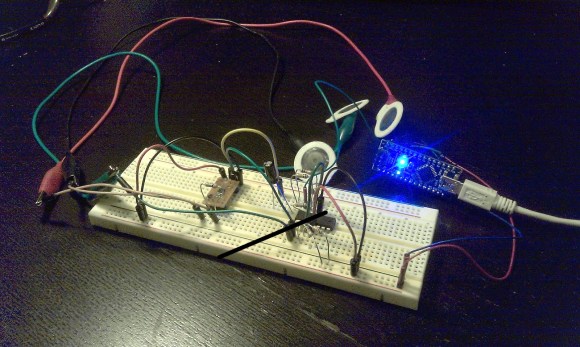
It’s difficult to image a more bare-bones approach to building an ECG. [Raul] used an Arduino nano to collect samples and push them to a computer for graphing.
An Electrocardiogram measures electrical activity around your heart. The white circles above are the sensors which he picked up in a box of fifty for 11 Euros (under $15). Stick them on your skin in just the right places and they’ll report back on what your heart is doing.
He used a AD8221 to amplify the signals. He mentions that this is an ins-amp, not an op-amp. We didn’t find a concise reference explaining what that is. It might be a good topic for the comments section. The signal from that chip feeds into an LM324 op-amp before being dumped into the Arduino.
Simplicity comes at a price. This measures very small electrical impulses and has very little in the way of shielding and filtering. Because of this you may need to do a rain dance, say a prayer, burn a candle, and stick needles into a doll to get a reliable signal on the other end.
Here’s another version that doesn’t require special sensors.


If you have a copy of the Art of Electronics by Horowitz & Hill you can get a great description of what an instrumentation amplifier is. If you haven’t, tut tut tut.
http://en.wikipedia.org/wiki/Instrumentation_amplifier
Ins-Amp == instrumentation amplifier.
An instrumentation amplifier is an arrangement of three op-amps so that both the inverting and non-inverting inputs are high impedance, the overall gain being set by a single resistor.
http://www.google.com.au/search?q=instrumentation+amp
Ins-amp = instrumentation amplifier = 3 op-amp arrangement with a differential input to eliminate most electric noise. This arrangement is normally used at electrocardiography,miographs, a other bio potential measuring equipment because of its differential inputs.
I’m a biomedical engineer I normally use ad620
The AD8221 is an improved version of the AD620
sounds like a balanced input on a XLR or TRS tpye audio input.
An instrumentation amplifier is a differential op-amp circuit providing high input impedances with ease of gain adjustment through the variation of a single resistor.
tl;dr
uses a varying resistance value to adjust the gain.
What’s an ins-amp?
Just kidding.
I’ve built an ECG before.
Poor use of English in title/article.
“Electrocardiogram:
The curve traced by an electrocardiograph. Also called cardiogram.
(Medicine) a tracing of the electric currents that initiate the heartbeat, used to diagnose possible heart disorders”
An electrocardiograph is a device for measuring/recording electrical activity of the heart.
An electrocardiogram is the reading/measurement made by such a device.
(Just like a telegraph is a device/system for sending messages,
a telegram is the output).
what about some patient insulation? AD202 anyone?
Instrumentation amp also explained in the AD8221 datasheet under “Principles of Operation”.
Ad8221 dataheet at http://www.analog.com/static/imported-files/data_sheets/AD8221.pdf
(Sorry, commenter devoured my email-style angle brackets around URL.)
Would it be possible to use those sensors to measure brainwaves?
The instrumentation amplifier (ins-amp) cancels common-mode noise. The classic book by Horowitz and Hill, mentioned above, explains how an instrumentation amplifier works. Commercial electrocardiographic equipment makes use of a third electrode, usually connected to the leg of the subject, in order to better control the common-mode voltage on the sensing electrodes.
When playing with equipment connected to the human body, ISOLATION from the AC mains is a big issue. For example, the Arduino board above is connected to a computer via USB, and let’s assume that computer is connected to AC mains. A fault on the motherboard of the host PC may cause the AC mains voltage to jump to the USB, frying the Arduino board, in turn frying the instrumentation amplifier, thus potentially electrocuting the subject.
Many oldie-but-goodie application notes from Burr-Brown—now part of Texas Instruments—discuss instrumentation amplifiers and isolation schemes. Although the components they refer to may no longer be in production, the ideas presented there are still quite relevant. Here is one of those app notes:
http://www.ti.com/lit/an/sboa064/sboa064.pdf
PS. This is my very first hackaday post.
Ok, um, aren’t those inputs supposed to be opto-isolated or something? Sure, the cheap switching transformer that came with your Arduino probably won’t develop a fault and shoots 240 volts into your circuit, but in the unlikely that it does you’re probably gonna wish that those electrodes you just strapped across your chest cavity are separated from the rest of the circuit by at least one layer of protection.
If you want to isolate something, do not isolate the inputs. The source has a very high impedance, and signals are in microvolt scale. You can easily isolate the USB, Olimex sells ready-made solutions for this.
go wireless.
include a rechargeable battery with a
non rechargeable backup for redundancy.
for safety,
add chargeport that can NOT be connected
while HumanInterface cables are plugged in
so that its impossible to plug in human while charging.
can you send me the whole circuit……