A while back we featured a magnetic rotary encoder that [LongHairedHacker] designed. The heart of the system is an AS5043 magnetic rotary sensor which runs from $6.5-$11 and has a 10 bits precision. As we wanted to check if his design was really efficient, he made a test bench for it.
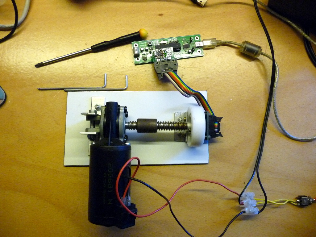
For 360 degrees, a 10 bits precision means a ±0.175º accuracy, which is quite impossible to check with conventional measurement equipment. The first approach he thought of was to attach a mirror to the encoders axis and point a laser beam at it. The laser beam would be reflected across the room to a big scale, but the minimum required distance would have been 5 meters (16 feet). So he preferred attaching a motor to the sensor, rotating at a given speed and measuring the sensor output.
In the first part of his write-up, [LongHairedHacker] lays the math which explains the different kinds of errors that should be expected from his setup and sensor. He then proceeds with his test, where an ATMEGA8 based board is used to send the measured position to his computer. It should be noted that [LongHairedHacker] currently uses the time spent between two received measurements on his computer as a time base, but he is planning on time stamping the data on his board in the next future. Nevertheless, he managed to measure an average ±0.179º accuracy with his simple test bench, which is very close to the manufacturer specification.
Here is the link to our original post about his sensor.


LongHairedHacker is also running a fundraiser for this on Tindie right now! https://www.tindie.com/products/LongHairedHacker/sindri-magnetic-rotary-encoder-1/
“For 360 degrees, a 10 bits precision means a ±0.175º accuracy”
There are so many things that are wrong with that statement that I don’t
even know where to begin.
Precision, accuracy and resolution means very different things and
cannot be used interchanably. Might want to read up on this
http://en.wikipedia.org/wiki/Accuracy_and_precision
>accuracy of a measurement system is the degree of closeness of
measurements of a quantity to that quantity’s actual (true) value.
>The precision of a measurement system, also called reproducibility or
repeatability, is the degree to which repeated measurements under
unchanged conditions show the same results.
The datasheet say:
Resolution * RES 10 bit 0.352 deg
Integral non-linearity ± 0.9deg (Maximum error with respect to the best
line fit) That’s with optimal magnet placement
Sorry about that and thanks for your comments tekkieneet :). People should read resolution then!
Why don’t you fix the writeup then?
Hi,
thanks for the heads up I will fix the technical terms as soon as my server becomes a bit more responsible again.
I have to admit that I didn’t look them up while I was writing the wiki article.
Also since English is not my native language and I’m studying computer science and not mechanical engineering it was a bit hard for me the find the right words.
So thanks for the heads up.
Sebastian
Im surprised you didnt take statistics in your CS program
I will use my psychic powers to determine that… He shops at american science and surplus.
Bam, mindblow.
Real men shop Russian Black Market.
How did he determine that the motor was spinning at such a constant, accurate speed to qualify it as a reference? Calibrating against a bad reference doesn’t result in much that is meaningful.
Hi,
as i mentioned in the wiki article, I ‘guessed’ it is ‘constant enough’ from the results.
If you take a look at the saw teeth in the first diagram I posted on the wiki (which should be reachable again now),
you can see that they are mostly identical.
Also if you look at the histogram where I compared the gradients between two samples,
you can see only a small variation there.
The variances motor speed can’t have introduced to much noise, otherwise there would have been a broader spectrum, unless the varying speed was cancel out by an other effect, which seems unlikely to me.
Greeting
Sebastian
You can vastly increase the “constant enough” or stability of the rotational speed by attaching a flywheel to the shaft.
Unless you are working with a worm drive gearbox (it seems so from the picture) that has enough gear reduction that the motor hardly would notice a fairly significant increase in mass moment of inertia at the output shaft. Remember that the inertia seen by the motor is decreased by the square of the gear ratio.
To be fair, I doubt (hope?) he never meant this to go up to unintended peer review, as I can only guess from the tact he takes in his answers. If this is just a playing in the workshop thing, then I just say “good job”, enjoy that someone even gives a passing thought to these issues, and move on.
Hi,
if intended to some kind of peer review thing I would have invested more time of course.
I just wanted to provide a rough estimate on the sensors resolution (see I did my homework on technical terms) and share my thoughts on it.
It was basically intended as some playing around to get a first estimate for the result and to get a feeling for the different issues that I’ll have to deal with.
Greetings
Sebastian
Hi,
as i mentioned in the wiki article, I ‘guessed’ it is ‘constant enough’ from the results.
If you take a look at the saw teeth in the first diagram I posted on the wiki (which should be reachable again now),
you can see that they are mostly identical.
So there can’t be too much variation in on 360° turn.
Also if you look at the histogram where I compared the gradients between two samples,
you can see only a small variation there.
The variances in the motor speed can’t have introduced to much noise, otherwise there would have been a broader spectrum, unless the varying speed was canceled out by an other effect, which seems unlikely to me.
Greeting
Sebastian
I just checked the linked article, and besides the aforementioned erroneous use of accuracy/precision I’m also not persuaded about the constant motion of the motor. The ‘average gradient’ is useless if you want to know the linearity error. The ‘roughly gaussian shape’ is a very liberal interpretation of measurement data, and the points besides the ‘average’ peak take up almost halve of the total number of samples. Looking at that data I would guess the motor is running faster,slower, faster, slower, etc.. thus creating a large peak in the middle and two ‘side peaks’.
Although the interpretation is very ehmmm.. ‘liberal’, it is a nice article. I would have loved to see the data from the sawtooth plot, but then subtract the ‘ideal’ completely linear sawtooth. Then you get a good look at what the error over time is, either in sensor or in motor speed… If the linearity error would be 20 bits over the 1024 bits you wouldn’t spot it in the plots provided.
Hi,
obviously you’ve got some more expertise in this field then I have and I really appreciate your feedback.
I know that most of my assumptions are a bit ‘liberal’,
mostly because of lack of time and equipment to do better.
What I was trying to is create the ideal sawtooth from the actual data,
assuming that I’m close enough to ideal thing to do so.
Of course generating the ideal signal and subtract would have been a better choice.
Also I don’t share your interpretation of the peaks.
I don’t think errors in the motor speed would accumulated in two nice peaks.
In my opinion this is rather an error introduced by the sloppy timestamping I used.
I’m already working on a better setup with proper timestamping and I’m planning to publish the raw data gathered with it.
So I’d really appreciate if someone here could provide me with a proper method of interpreting that data.
I’m definitely going to subtract it from an ideal signal this time, thanks for the hint.
Sebastian
One idea: you don’t need timestamping if you’re sampling at a very precise interval. Depending on the type of controller you’re using you can use a timer interrupt to read the data. After that you only have the jitter of your clock versus the clock in the magnetic encoder that will add error (do you know whether the encoder takes a sample ‘on demand’ or with a free-running ADC?)
I’d love to hear about the follow-up!
And another idea is to use an optical encoder on the same shaft, and sample on every (or every xth) pulse of that encoder.
Sebastian,
I see some people are being what might appear to be “overly picky” in this peer reviewed journal…. ummm, I mean hack-a-day forum :-) At first I was getting a bit irratated, but then I realized that this sort of thing goes on all the time in “peer reviewed journals”! It is necessary for good science. I understand that your experiment was to see if it was good enough for what you wanted it for, I think some of the crititism was that whatever good enough is, it wasn’t defined for them. Anyway, thank you for sharing your work, and even more, thank you for taking other’s suggestions to make your results more meaningful and accurate (precise? more resolution? Umm… never mind… just trying to make a pun here :-).
This hack-a-day project has inspired me to look into this sensor some more. For what I’d like to make, I would only need about 1 deg. resolution, and would love about 1/3 degree precision. Looks like this sensor has a fighting chance!
– Steve
p.s. I’m thinking of a jig/fixture for grinding lathe tools. I know dozens of “real” machinists who have enough practice to grind them by hand and make them amazingly sharp. I don’t think my eye is that good, and I don’t have enough hobby time to get enough practice to do as well as they do. So I’m hoping to make a jig to hold the dimensions constant while I experiment to see what angles I end up liking.
As was alluded to above, the RESOLUTION of the encoder is the smallest change in angle that the system can detect (‘resolve’). For the specs you quote, it is 360 degrees divided by 1024 (or 2^10) which is approx. 0.352 degrees.
This says nothing about the ACCURACY or PRECISION of the encoder. It can have an incredibly high resolution but still be extremely inaccurate and/or imprecise.
It’s also good to keep in mind that the manufacturer suggests using diametrically magnetized magnets for better performance.
Nice gadget
When exactly is the -next- future?
Ceiling fans look pretty constant to me. Remove the fan blades to reduce deceleration. Spin it up, and turn if off to eliminate torque ripple. Quick, easy, and probably good enough.
I’d check it with a Moore 1440 Precision Index, good to ±0.1 second of arc at its 1440 indexes. A lesser, older turntable would probably work too, If you wanted to only check less than 90, a sine bar and some good calibrated Johansson blocks would do. Tedious that way though.
Mechanical precicion and accuracy over mass produced electronic components.
A Surveyor’s Transit also has relatively high angular precision, Around 1 minute for transits, or around 0.1 arcseconds for a newerTheodolite (say VietNam War era)
What about taking a fixed, known length of rope and running it over a bearing attached to the shaft of the encoder? Knowing the circumference of the bearing, and the length run, you can see how many times the shaft turns. With that, you can compare the number of times the shaft actually turned vs how many times it should have turned, and you should be able to figure out the difference from that.
Awesome gadget, must be fun to use.