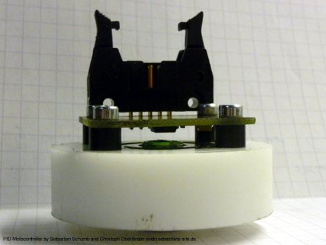
[Long Haired Hacker] has undertaken a high-resolution 3D printer build. He got his hands on some motors to drive the build platform but it doesn’t have a built-in encoder. He knows that optical encoder wheels can have problems due to dirt and grim as well as ambient light so he set out to find a better way of providing feedback to the controller. He ended up building his own magnetic rotary encoder which is shown above.
At the heart of the system is an AS5043 magnetic rotary sensor. The chip, which runs from $6.50-$11, can detect and report the rotation of a magnetic field with great precision. The rotation data can be read out in degrees using SPI, but it sounds like there’s also grey code output on a few pins if that suits your needs a bit better. The magnet which the chip measures is mounted in a sleeve milled to seat inside of a bearing ring.
The 3D printing method [Long Haired Hacker] has chosen uses a projector and light-cured resin to achieve the kind of results seen in this other hi-res printer.


Just a minor correction. I’m assuming you meant to say “dirt and grime” instead of “dirt and grim” (unless you really did mean to suggest that a modern decedent of the famous fairy-tale recorders is going around sabotaging optical encoders. In which case, it should be two ‘m’s and you forgot to capitalize the ‘G’.).
To continue the pedantics, it’s a Gray code not a grey code.
It’s not the colour grey but the some guy it’s named after Mr Gray I guess.
That is a Mr Frank Gray (13 September 1887, Alpine, Indiana – 23 May 1969) according to Wikipedia.
I’ve used the Renishaw magnetic encoder modules and found that they work like a charm as long as the magnet is carefully positioned.
So, this wouldn’t work very well if the magnet and sensor aren’t both centered on the axis of rotation?
I have found that the device is somewhat tolerant of the magnet and chip not sharing the exact same axis of rotation; so if your magnet is offset from the axis of rotation slightly that is okay. However I have also found that the chip and magnet need to be plane-parallel and that the distance separating the two needs is important. From the datasheet of the part I’ve used:
“NOTE: For the accuracy specified the center line of the magnet
needs to be square to the chip within 2° and aligned within
the center of the board ±0.1 mm (mid point between the 2
mounting holes).”
The +/-0.1 mm alignment is easier to achieve than the 2deg plane alignment if you’re limited to a drill press and hand tools.
Datasheet Link:
( http://resources.renishaw.com/en/details/Data+sheet%3A+RMB30+angular+magnetic+encoder+module%2833737%29 )
For the life of me I can’t imagine how the chip is positioned. Is the wheel enveloped somehow?
The chip is centered on the axis of rotation with the top facing towards the wheel and the circuit board is affixed directly to the wheel with screws.
The magnet goes on the end of the axle, inside the bearing, a few mm from the top of the chip.
someone please sell me lots of these. Screw stepper motors and all their associated electronics :3
That green coat spray looks awesome:
http://bungard.de/index.php?option=com_content&task=view&id=65&Itemid=46&lang=english
Are there any alternatives to this? Possibly one that could be purchased in the states?
I’ve played with a bunch of the AS504x chips. The 5040 will output quadrature encoder, so it can plug straight into a servo amp like Gecko’s. The 5045 only has SPI output but having 12 bit resolution is pretty cool. I have arduino code for both the ’40 and ’45 here: http://madscientisthut.com/forum_php/viewtopic.php?f=11&t=7 and do sell the chips on breakout boards as well. I’m just finishing a version that’ll fit inside a small sparkfun RC servo and replace the potentiometer — but hoo boy there’s not much room inside that little plastic case. You need the magnet centered on the chip, but the chip has two LED outputs that will visually tell you when it’s aligned correctly. It’ll also give you good output up to crazy rpm’s. They work beautifully for robotics and CNC control.
Also, findchips.com is a great starting point for finding good prices; I’ve found Component Distributors International and Future Electronics have the best prices on Austrian Microsystems chips.
Not to be a twat or anything, but it strikes me that a magnetic encoder is a step backwards. Mainly because the automotive industry (who used magnetic encoders for decades) now use optical encoding for engine RPM and engine bays get a lot grimier than most things. Missing tooth encoding may be a better option.
Hardly a step backwards, its more likely that the optical encoders are more tolerant to power spikes.
If you’re interested… there is a commercial hobby servo, the Robotis MX-28, that uses the AS5045 magnetic encoder. There is a teardown over at Hizook.com where you can see how to layout the mechanical construction. The basic gist… it’s higher resolution that a cheap shaft encoder, and much less expensive than an optical encoder.