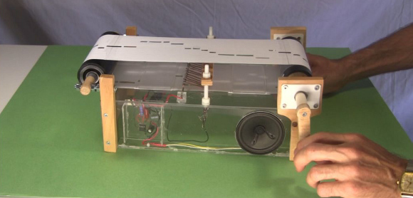
For the Ottawa Mini-Maker Faire this year, [Steven Dufresne] created an electronic take on the classic mechanical music box.
A typical music box uses a sequence of bumps on a rotating drum to pluck the tuned teeth (called lamellae) of a metal comb. Steven ditched the drum and comb and replaced them with a strip of paper and a single 555 timer. The timer is configured as an astable oscillator with a fixed capacitor and charging resistor. The discharge resistor is selected via a series of 13 shaped wires that drag along the strip of paper. When a wire drags over a hole, it is connected to a copper pad below that is soldered to a specific resistor. This completes the circuit and generates a tone specific to the resistor selected.
While the electrical aspects of the project are fairly simple (not even requiring a circuit board), the mechanical parts are much more sophisticated. Steven had problems getting the dragging wires to make good contact and keeping the paper roll pulled tight. He outlines all of these challenges and how he solved them in his very thorough video summary (embedded after the break). With all of his incremental improvements to the design, the finished music box stood up to a whole 14 hours of abuse at the Faire.


It sounds like a Crumhorn, awesome.
Wonder why designs like this never used a motor to make it rotate automatically?
Just a guess, but hooking http://hackaday.com/2013/09/11/switching-leds-with-motors-on-a-led-strip/ up to allow software controlled generation of sound out of glasses filled with water would have make for a better use of rotating motor(s)?
I was thinking of motorizing it but I ran out of time before the Maker Faire. I’m glad I didn’t motorize it though. The visitors to my booth all delighted in cranking it themselves. The kids’ hands were reaching for the crank even before they got to the booth!
Very nice work.
I would have used LDRs in series with the discharge resistor and cut slots in the paper… but way to go, lovely job.
Follow-up should be software to generate music from midi file
errr… from midi file using a cnc or vynel cutter.
Thanks. I’m glad everyone likes it so much.
I did kinda slap my forehead when someone first pointed out using LDR or LEDs with photodiodes. With all the interest and neat suggestions, I may just make another one.
Not analog enough… should replace the 555 with just RC OSC circuit! :)
indeed
Although a 555 timer IC has one set, reset flip flop in it, a 555 timer IC is still mostly linear. So I’d consider a 555 a linear IC. I even keep my 555 ICs in a drawer marked Linear ICs. Linear is not digital, so that makes a 555 timer IC an analog mostly chip. I suppose the case can be made that a 555 IC is an analog to digital converter though. Then again an RC oscillator circuit could be called a digital clock circuit too.
Now if you’d said not discrete enough I can’t see any arguing with that. There is something novel about making a circuit today and not using any chips in it at all.
I still like the project. They probably could have used photo transistors instead of the mechanical switches. Someone else mentioned motorizing the tape. That might have been nice too I guess. I can see the appeal of hand cranking it myself.
Replace the 555 with this one from EMSL.
http://shop.evilmadscientist.com/productsmenu/tinykitlist/652
Don’t forget the paper reel; that’s digital information it’s reading.
Now all you need is a monkey and you have your own business! Maybe he should have used duct tape for the actual roll itself, would last longer and take more tension, still cool though. Oh, and its not Ottowa, its either Ottawa or Oddawa, your choice.
Would have been multiple sticking points. ;)
Two pieces, adhesive sides together.
Since the notes on the ribbon represent either an On or Off condition,
it is not “completely” analog.
B^)
Ottawa, not Ottowa eh.
Not ah, wah, now try it again!
Wish Hackaday was around 50 years ago when I built one of these – but I had it easy – I had a proper erector set for the mechanicals, and 2n107’s for the oscillator