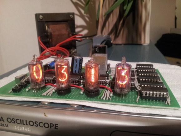
Here is a very nice project that [Znaxque] finished a few months ago: a simple nixie clock made with logic gates only. In this build, the mains 50Hz is used as a time base instead of a 32KHz crystal that most readers here may use. In the very long term, this clock may actually be more precise than a crystal-based one as power companies in Europe adjust the mains frequency. However, at a given moment the difference between this clock and a reference may be as big as 60 seconds.
The design was sketched on a simple piece of paper and later made using salvaged ICs. [Znaxque] only bought the six IN-14 nixies for $45 and the veroboard shown in the picture above. The BCD to Decimal decoders are 74141s and three buttons are present on the board to set minutes, hours, as well as resetting all the counters.


In the long term true, but keep in mind the mains frequency changes pretty sporadically as the load changes. This guy has some cool info on the subject: http://wwwhome.cs.utwente.nl/~ptdeboer/misc/mains.html
Oh noes! the clock will be out by max 1 minute.
Let’s face it, you’re not going to use this clock for really time critical stuff where every seconde counts. And over half a year it will be a hell of a lot more stabil than a RTC IC with an average 32 kHz crystal.
Ofcourse if you want nerd points (let’s face it, we all want those) use GPS combined with a rubidium standard. But then again that’s who needs that kind of precision from a normal desk clock?
Nobody said 60 seconds deviation wasn’t acceptable. It’s just something to keep in mind.
the second link I put is actually pointing to yours ;)
I love the use of CerDIPs in this build…nice!
Cool project! Have to laugh at the phrase “The design was sketched on a simple piece of paper…. ” Versus a complicated piece of paper…? Ha!
At first sight, that timebase seems convenient. However, in time, the clock will always be fast. The problem is that small interference spikes occurring around the zero-crossing point will add to the number of transitions (never subtract!) counted during the day.
I suggest that the inverter should be slugged so that it will not respond during the time that it takes the AC signal to pass between the thresholds. I guess that a 20-30 ms time constant should do it.
Oops! That should be 5-10 ms!
I ran across this very similar design on the internet, I cant remember where but I posted it on my flickr account:
http://www.flickr.com/photos/67292116@N00/8224180085/in/photostream/
It has a AM/PM indicator as well. My plan was to use the 1PPS output from a cheap GPS chip to provide the timing signal so I could just use a small inverter to drive the lamps off something other than mains.
I’ve seen about a zillion Nixie Tube clock writeups all over the place… Can’t remember where it is, but if you ever see it, check out the one that the creator offers as a kit, complete with a hardwood box to put it in. I was amused.
mmm logic porn