[Paul] recently purchased an inexpensive USB power pack, hoping to use it for powering small electronics projects. Unfortunately it has been designed to only stay on when a device is drawing a lot of power (like charging a cell phone), so he set out to fix it.
He started by experimenting to see just how much current is required to keep the battery pack on, and for how long. Testing a few resistors he discovered that a 22 ohm one will keep the power supply on indefinitely. If there’s no load, it only remains powered on for about 13 seconds. Now you can’t just hook up the 22 ohm resistor to a 5V power supply for the sake of keeping it on — that would draw 1.1watts and get very hot!
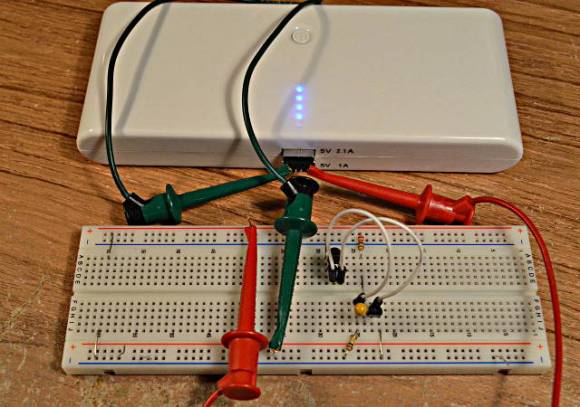
His next step was to determine how long the load needs to be on for, and at what interval in order to keep the power supply active. He created a test circuit using a Teensy microcontroller and determined that a 20ms pulse every 1.4 seconds was enough to keep it on — any less and it would switch off after a few minutes. The final transistor based circuit draws about 222mA — but at a 1.6% duty cycle, resulting in only a 3.5mA draw! [Paul] suspects the switching power supply inside battery pack probably draws more than that! He can’t take all the credit though, he learned of the idea from a forum post — but he certainly has made a very nice write up for people to follow in his footsteps!
Now that’s a good old fashioned product hack!


couldnt you just crack it open and connect wires directly to the internal battery?
Only if you wanted 4.2-3.7V instead of 5V. And either the batteries had an integrated overdischarge circuit xor you were okay with them spontaneously dying one day after you drew a little too much charge off them.
Probably not, as these battery packs usually contain Lithium-ion rechargeable cells. They would be regulated by the PCB inside the pack, and you could cause major damage to the batteries/your connected device if you just wired directly to the batteries. Great hack!
Paul here (who made this little hack). I tried opening it. There’s 1 screw on the back, but even with that removed, the case appears to be *very* securely glued shut. After plying in a couple places and marring the plastic with no sign of the seam budging even a bit, and without a 2nd unit, I decided not to wreck the case trying any further.
at only $20 (chump change) it very affordable to ruin one and buy another
I did order another one. It hasn’t arrived yet.
Why wouldn’t you order a different one that doesn’t require modifications to supply power at low currents?
Actually, I did that too. Or at least I tried, with a smaller $15 one. Of course, they give no indicate if it automatically turns off. But if it doesn’t automatically turn off, I sure most people who use it to recharge phones would be unhappy, so my guess is most of them will automatically shut off. Of course, there’s no specs other than capacity and max current.
That smaller $15 also has not yet arrived.
Paul, that’s a well written description on your site. Now the all important question, whose pack is that? It resembles the one that Adafruit sells, but, ah, I’m not certain of that.
I got it from a no-name Chinese merchant on Ebay.
Just search for “power pack” or “50000mAh USB Battery” on Ebay. You’ll see LOTs of those merchants all selling the same thing, all about $22 to $30.
Oh.
Ebay and I are not friends today. Every time I try to find something it returns hits that do not match. But okay.
50000 :DDD
it used to be “30000”
http://goughlui.com/?p=4321
in reality it is 4000mAh = those cells are 500mAh !!!!!
its better to just buy USED laptop battery pack with sanyo cells, even 1 year old used one will have at least 2x capacity
I can bet you more than likely that pack might be held together like a dell power supply
they use the sonic welding technique where the plastic gets melted by the high frequencies, it’s not worth trying to open it, you’ll cut your hand a few times prying quite a lot in all different ways
Bought one with an integrated micro USB cable to charge devices and a free USB port for other cable types. Wanted to use it to run a bluetooth audio receiver in my car. Same thing, wouldn’t continually power, only charge a battery. I just plugged the integrated micro cable into the battery charging port and , viola, tricked it into doing the same thing as this hack.
Great hack, but it looks like the HaD writeup is short a few of these: !!!!!!!!!!!!!!!!!!!!!!
Oh my god you guys. This may be the first time nobody can say “Not a hack”.
Connecting a load to a power supply? Not a Hack.
Meh, seems like a hack to me.
I did the same trick with some 100 ohm resistors. 2 in parallel, 50 ohms, did the trick with 1 / 10’th of an amp. Way better than 1 / 4 of an amp in the original case. The Teensy trick with 1 / 3 of the drain of my easy solution is all the better. If you use a big one with a 2.5 amp outlet the resistors is only a 4 percent hit, comparable to the Teensy on a 1 amp outlet.
Either way, you can adapt all manner of portable electronics to lithium ion batteries without endangering yourself (and your building!) messing with the incindiary things. In either case, put a switch before the Teensy or (47 ohm) resistor to shut off the device, and the power bank quietly shuts off too.
Finding a way to use something for something other than its intended use.
I call that a hack.
Of course they are glued tight when it is meant to hide what is inside:
http://www.geek.com/news/buyer-beware-unbranded-battery-packs-may-be-full-of-sand-1544064/
or maybe filled with marijuana ?
So, color me stupid, but I don’t understand how the circuit is supposed to oscillate and neither does my SPICE program. On initial power on a voltage difference starts to build across the cap; once that voltage difference exceeds the Vbe for the PNP it turns on which turns on the NPN drawing current through resistor and brings one end of the cap near ground but then it never turns off…is this just exploiting a non-ideality or am i missing something?
It is not really a robust circuit. If the PNP stays on too much, the NPN will stay on, and circuit will rest with the PNP on (fed base current by the 100k), supplying base current to the NPN (say beta*(5.0-0.7)/100k ~=4.3 mA — this turns the NPN on hard, saturating it. The circuit can stay there. If there is some base-emitter leakage in the PNP (or an additional base-emitter R), the PNP will begin to turn off (or at least not run as much current, thus causing the NPN to run less current (or at least not saturate as much), causing the collector to rise, coupling via the cap to the PNP, turniung it off more etc.
It’s a very picky circuit — depends a lot on beta, transistor saturation behaviour and the precise ratio of R’s connected to the PNP (and temperature). I suspect Paul’s battery pack stopped because this circuit quit eventually.
Note that the circuit can quit with both devices on, running a lot of current continuously. Best to use an LM3909, 555, or 2-NPN multivibrator.
To clarify my previous comment — if you are trying to build this or simulate it: to prevent latchup, you need the ratio of the two resistors to be higher than the product of the gain of the two transistors — so if the NPN beta was 200 and the PNP’s was 100, you’d need 200*100, or 20,000:1. With a 22 ohm load, you would therefore need over 440k — so 1 Meg would be a good starting point.
In SPICE, oscillators like this may not start — you can help by either pulsing the supply on (use a pulse or PWL source), or setting an (actually nearly any) initial condition on the capacitor.
The off time is proportional to RBIG*CAP; the on time is not easy to calculate and depends on nearly every component, but can also be controlled with the load R (RSMALL). Note also that in this circuit, the voltage across the capacitor changes from positive to slightly negative (by the base-emitter V of the PNP), and this is not ideal if you are using an electrolytic capacitor (connect its ‘+’ to the NPN, the ‘-‘ to the PNP).
Note also that the peak curent from the supply is greater than the current in the NPN (which is limited by the RSMALL) — the PNP’s (large) base curent also flows from its emitter, and this can exceed the NPN’s current.
Remember again — in this circut, if the ratio of the resistors isn’t high enough (including as temperature and supply voltage change), the circuit could latch (and burn) up.
for those who want to bother cracking the unit open
http://www.youtube.com/watch?v=C3YksbvYnKY at 6:30 he starts talking about the power supply/charger and how to open it up
from the http://hackaday.com/2013/11/04/manufacturer-crippled-flir-e4-thermal-camera-hacked-to-perform-as-high-end-model/ video there is a link to the review
That is awesome!
why not just open it up, find the current sensing resistor and replace it with a higher value?
Or just find the measurement point and feed voltage into it even at no current draw, that way you don’t get the voltage drop over the sense resistor either.
I had the earlier variant of these same packs, used the internal cells for a short lived E-bike mod.
Turns out that they are current limited for a good reason and it nearly went up in flames but settled for destroying several of the tabs :-( Still haven’t dared try and use it since but the cells are safely stored and discharged to 3.4V each.
Thanks for the tip, as I also have the PCBs taken off said batteries and keeping them turned on with no-load would be handy.
You might want to check if the battery starts with a 10µF capacitor connected, according to the usb spec, a usb host can check for connected devices by measuring capacitance on the usb power rail.