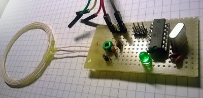
[Nicholas] built a simple NFC tag using an ATtiny84 microcontroller, four resistors, three capacitors, a diode, and an antenna. It implements ISO 14443-3, a standard for identification cards, and can communicate with the NFC chip sets found in most new smartphones.
This standard uses on-off keying for communication, which makes the hardware slightly more complex than the AVR RFID tag that we saw a few years back. The antenna and a variable capacitor form an LC circuit tuned at 13.56 MHz, which is the carrier frequency for the protocol. The diode acts as an envelope detector, letting the microcontroller recover the signal.
It may not be fully compliant with the standard, but [Nicolas] successfully tested out the device with his Lumia 620 phone. The firmware is available on Google Code so you can program your own tag data into main.c, build the firmware, and send some NFC packets. You can also check out a demo of the device after the break.


This should probably be called DIY NFC reader. NFC tags are passive. Where as this is more like what you’d find in a smart phone itself. Either way it’s pretty cool, I think I’ll build one and i’d like to see his code stay as in-line with standards as possible.
It’s correct to refer to this as a tag: It’s passive (meaning it doesn’t generate a field to send data) and implementing the PICC side of the conversation. However, it’s *not* passively powered from the field, and also independently clocked (his writeup mentions problems matching the µC clock to the carrier clock), so it’s more of a tag emulator than a fully passive tag. The original inspiration Nicholas links to, http://scanlime.org/2008/09/using-an-avr-as-an-rfid-tag/, is actually a fully passively powered and clocked tag.
This thing is not able to read the passive nfc tags, instead it emulates such a passive tag.
Okay, so it’s a tag emulator. What would it take to make it a writer?
Active or passive it emulating an NFC tag. It does not read tags.
Interesting. I wonder what it takes to build the other end that reads it.
Neat, maybe someone can use this to store keys in case they lock themselves out of their phone etc.
NFC to 433MHz bridge would be handy.. can you say “Auto unlock/lock of vehicle with proximity” ?
hello how can I build a powered antenna to increase the range of my nfc?
Hello, I am interested in building this simple NFC tag for hobby. I was wondering, I tried to create the circuit using the schematic you have on the link. But it seems that I could not get the expected output from the circuit before connecting it to microcontroller.
were the components you used the same as the one from the schematic? Thank you
If I wanted to try out different antennas to test with this circuit, I’m assuming I would only have to tune the variable cap so the antenna resonates at the 13.56MHz ? Would this be the correct approach?