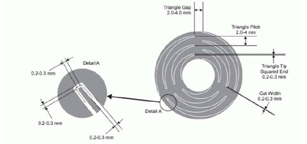
Recent experiments with the Arduino CapSense library led [Bryan] around the Internet looking for interesting applications. He hit upon a very cool touch scroll wheel made entirely with PCB traces, but the geometry – three interleaved zig zags is impossible to build in the decidedly ungeometric Eagle PCB package. One thing leads to another and now [Bryan] has a cap touch wheel Eagle part designed entirely in OpenSCAD.
The touch scroll wheel implementation [Bryan] found came from an ST touch controller datasheet and used oddly-shaped patterns to create a capacities sensor. Eagle is terrible for designing anything that isn’t laid out at a 45 degree angle, so he fired up OpenSCAD to draw these triangles. Importing into Eagle was another challenge, but a quick Ruby script to convert a DXF file into a set of coordinates for Eagle’s POLYGON command made everything very easy.
If OpenSCADing touch sensors isn’t your thing, there’s also an Eagle library full of them – something we found last week.


TOS do not allow 3rd parties to post the app notes.
That pdf website DMCAnt do that…
In other news, you can use a hammer to crack a nut.
Well, if the maker had a dxf files, its easy, Load the dxf into a laser engraver, coat the PCB with two layers of matt black paint, and burn away those tracks. Etch, Rinse. Populate.
Capacaties sensor?
it senses your capacity to spell
does anybody have a link with an example of how to use such a capacitive touch wheel with avr/arduino?
I would love an angle to this story… like… why? To avoid click on a scroll wheel?
It’s arranged this way so that you get an interpolated position between sensors. If you had only three ‘pie’ wedges then you’d get full signal when your finger is anywhere on the main part of the wedge, then a rapid drop-off as it left one wedge and moved onto the next wedge. Similarly, you’d get a rapid increase in signal as your finger arrived on the next wedge.
This is fine if you have many sensing wedges around the circle. Maybe 8 or 12 or 16 would be a nice number. But in that case you will have 8, 12 or 16 traces, I/O pins and capacitive sense circuits, which costs money.
By physically interleaving the sensors like this you can get away with fewer sensors (therefore cheap) and you can interpolate the finger position by looking at the relative values of the two sensors that are detecting a signal (the third one gives you a handy ‘no touch’ baseline).
So, that’s why.
If your PCB software can do arcs, with just a little math you can do this – I managed with a 20 year old version of TANGO and it took all of 5 minutes to duplicate it. [3 points describe a circle, or an arc.]