There are dozens, if not hundreds of examples around the Intertubes of an Arduino generating a VGA video output. The Arduino isn’t the fastest chip by far, and so far, all of these VGA generation techniques have peaked out at lower resolutions if you want to control individual pixels.[PK] has an interesting technique to generate 640×480 VGA at 60 frames per second without overclocking. It’s hacky, it’s ugly, but surprisingly, it actually works.
The VGA standard of 640×480 @ 60 fps requires pixels to be clocked out at 25.175 MHz, and the ATMega chips found in Arduinos top out at 20 MHz. [PK] wanted to generate VGA signals without overclocking, He did this by doubling the clock frequency with digital logic. The ATMega generates a clock, an inverter delays that clock so it is 90 degrees out of phase, and the two clocks are XORed, doubling clock output of the micro. It produces a very ugly square wave at 32 MHz – an error of 27% compared to the VGA spec. Somehow it still works.
With a hilariously out of spec clock, the rest of the project was pulled together from [Nick Gammon]’s VGA library, a 16×16 font set, and a project from [lft]. Video below.


That’s really nice if I don’t have a Parallax Propeller around (not snark, the Arduino is easier to buy locally).
Possible Clean Up?
So in theory if you repeated this process you could get a 64MHz signal. Then if you used any of the various latching components that change on a clock cycle, you could get a “near perfect” square wave out. Now duty cycle may be off still depending on the original wave, but would be a lot closer. Parts would have to operate fast enough though. The reason for the second doubling is that this would halve your frequency.
You can actually go one step further: 128 MHz with 1 bit color (we can rotate through 8 bits during every ‘real’ clock). 74.25 MHz is the pixel clock for HDMI 1080p @ 24Hz, so hopefully someone does black and white in full HD next.
Thinking a little more, you wouldn’t even have to repeat the process, if it was XOR’d with a faster signal to start with I think. So if you XOR it with a much faster signal, use latches to clean it up, then in theory if you can build it with fast enough parts, you could get a fairly reasonable picture fairly easily.
It’s a very “ugly” way to double frequency, and while it may be possible to double again, it is not guaranteed to work. The problem is that the function is dependent on the logic delays and they can vary a great deal, and not only according to the logic family used. Better would be to start with a higher frequency clock source and divide that down for the processor as needed. If clock frequency multiplication is really needed then a simple PLL circuit could yield better (and more flexible) results.
Yes, microwave transmitters often multiply their LO from a low frequency source. The multiplication method used in the project is somewhat dirty though. Often they simply send the source signal through a non-linear amplifier and filter out the wanted harmonic.
So its over clocked, just not by traditional methods?
no, it just doubles the clock signal to the display
What’s the point of that? the Arduino isn’t really outputting 640×480 at that point, it’s doing 320×240 with pixel doubling basically?
You can already do 320×240 without needing useless circuitry.
Think of it more like pushing out 2 pixels on every 16 MHz clock (the rest of the logic just switches between the two). So, you can have 4 bits of color at 640×480 pixels, all individually addressable.
No, the ATmega chip on the Arduino is still running at stock 16MHz. This is not overclocking.
Technically, the chip is specced (by Atmel) to run at up to 20MHz (IIRC), but Arduinos come with a 16MHz crystal on board instead. Because legacy reasons.
Stupid question, but what happens if you generate the signal at 12.5875 MHz?
Most monitors won’t sync that low. There are some modern LCDs that’ll sync to arcade signals, and maybe an an old arcade monitor might be able to do it, but it’s way outside VGA spec. Also you’d have to drop resolution and/or refresh rate.
I presume Skitchin meant running the Arduino at 12.5875MHz, so that the frequency-doubled signal would be at VGA-spec 25.125MHz. I expect that would work, but any timing-related constants used might have to be modified. As I understand it, when you tell an Arduino to wait a millisecond, that compiles to code that waits for 16000 cycles.
Also, it would require physically modifying the Arduino.
All true, but if you are getting VGA out of your ‘duino like this, sticking a crystal and a IC together and then programming it all in assembly isn’t out of your reach.
“The Arduino isn’t the fastest chip by far /…” – maybe that’s because The Arduino isn’t a chip at all? Write once, read twice? (before publishing)
Actually yes, it is most certainly a chip. Don`t let the fact that it comes in a board for factor fool you. Almost any arduino board can be boiled down to a chip and a crystal, or just a chip if you mess with the boot-loader (and use the internal occilator). I actually bought a bunch of ATMEGA328`s in order to build a bunch of mini-ardunos.
On an unrelated note, I read (and thought) the DUE was fully capable of decent VGA…
The ATmega is a chip. The Arduino is definitely not a chip. That’s what Chris was getting at.
What makes it an arduino is the bootloader.
True, the Arduino is a chip and Visual Studio is a computer.
Well, in a way, it is, isn’t it? ;-)
It is a chip, it’s just one that’s conveniently broken out for you that has a FTDI, crystal and regulator built in.
Agreed, Arduino isn’t a chip.
Arduino is a bunch of code that runs on various microcontroller chips. The way this article is worded though makes it sound like there’s only one chip Arduino runs on. There’s what, a dozen officially supported ones, and probably hundreds of ports.
This further illustrates the need for more bandwidth and more capability (and smaller feature size and more “horsepower”) for Arduino and Arduino like boards.
While keeping them at a reasonable price. Yes, I know you can buy $200 stupidly awesome boards but they are a pain in the ass to program for and not easy to find and tend to dry up and get discontinued often and overall are not terribly great to work with unless you really, really have to.
It wouldn’t mean squat even if the “stupidly awesome boards” sold for $15 a pop if there’s not enough adoption.
Re: MSP430 Launchpad, it’s the same concept as an Arduino, but it has a much smaller following.
The teensyduino has a 72mhz processor and 256k of memory. That’s a big step up.
Of course, only if you want to output data to a VGA monitor, which isn’t really all that useful to start with.
We’ve seen over 20MHz over clocking on Atmega 328’s: http://garagelab.com/profiles/blogs/atmega328-overclock-30mhz. Also, one could try to use 4 Arduino’s (1 for a controller and 1 for each color (RGB)) and possibly get ~512 colors.
Nice Hack! :-D Still think a better approach would be to use serial RAM and some external logic. Here’s what I’ve done using an 8051 microcontroller, but the basic principle would still apply to Arduino/AVR: http://fleasystems.com/fleatiny.html for circuit schematics and also a video demo.
I did something similar on my Veronica computer. In my case, the limiting factor was I/O bandwidth. The ATmega uC runs at 20MHz, but the I/O ports can only be driven at half that (10MHz). Still, it was enough for a high quality VGA signal with 8-bit color entirely by bit-banging. I limited the resolution to an arcade-like 256×240, because it made rendering code dramatically simpler for the 8-bit CPU.
http://quinndunki.com/blondihacks/?p=980
Your project was one of the ones I read cover to cover when I was designing this ‘thing’ – thanks for going into such detail on your build!
Without the AVR being over clocked I’m struggling to figure out how this should output anything close to 640×480, or is it just using scan doubling? if so what’s the point
Now can someone build an HDMI variant?
It would be hilarious to do this to someone’s TV without them knowing, drawing flea power from the e2prom lines to recharge its internal ORB cell then wait for an appropriate signal and display a copy of the BBC News “Zombie Attack” from a film or something :-)
This might be a “Fail of the Week”.
That library produces 60 pixels per line in 3-bit color mode at 16MHz processor clock. It needs 6 clocks for one pixel.
Is there any way to clock out one byte per clock on an ATmega? I don’t think so.
It’s an 8 bit processor, so you’d have to use more external logic to get more than 8 bits per 16 MHz (or just overclock it). One way would be to have external RAM and get your color data directly from the RAM – but at some point, the ATMega is just a clock and no longer in control… it’s a philosophical question at that point.
This article got me thoroughly confused at first. My try at explaining what’s going on:
This project defines one byte as 2 pixels, e.g. high nibble = even pixel, low nibble = odd pixel. AVR thus can write two 4-bit pixels at once into the external latch at a lazy pace of 1/2 pixel clock. External pixel clock, which is the double of AVR main clock and is not too far from accceptable value of pixel clock for 640×480 mode, switches the nibbles in the latch, thus producing individual pixels at full rate.
There is no such thing as “pixels” in analog VGA signal. You just have to meet the timing requirements of sync signals and blanking porches, the rest is technically analog, continuous. So “pixels” can be shifted out at a slower pace, they will simply stretch. Modern monitors would try to correct it to one of the standard resolutions though so it’s not guarranteed to look well.
Same idea could be extended to 4 8-bit shift registers with latches and parallel load. Thus by writing 4 bytes AVR could offload data for eight 4-bit pixels, saving itself more time for processing. And by connecting the output of shift registers to a small 4×8 RAM and a DAC, this monster would get a programmable RGB palette.
For whatever it’s worth, the 32MHz dot clock given here is probably close enough to the 31.5 MHz used by 640×480@75Hz and the 33.75MHz used by 848×480@60Hz that it might be better to use those modelines instead of this weird compressed 800×480 mode that doesn’t display right on LCD monitors.
Not 640×480. It’s got 480 lines, sure, but calling it 640×480 is a stretch. This is the magic of analog — it’s probably closer to 60×480 than 640×480, but it’ll display on a monitor that does 640×480 because there’s no pixel clock on VGA (it either just shoots the analog stream out the CRT, or samples at a regular rate it guesses at for an LCD).
You should try putting something together using my example – this is a real, full, 640 pixels wide, and that ugly flashing message comes from a 16 pixel wide font (I have a message generator script in the linked piece so you can try it with your own message to verify). If it was only 60 pixels wide, you’d only see 3.5 characters per line.
The pixel clock for industry standard VGA is defined as 25.175 MHz, so 32 MHz means you put out 640 * (32/25.175) ~= 800 visible pixels, and 640 are sampled.
Try to display 16 different pixels in one line right next to each other.
Do it 50 times in one line. This will be 800 pixels.
Sorry. There are only 8 colors. So it should be 8 different pixel – 100 times in a line (or 100 different Characters with a 8 pixel Font). The 16 Pixel Font does not prove anything, except when you are displaying Chinese.
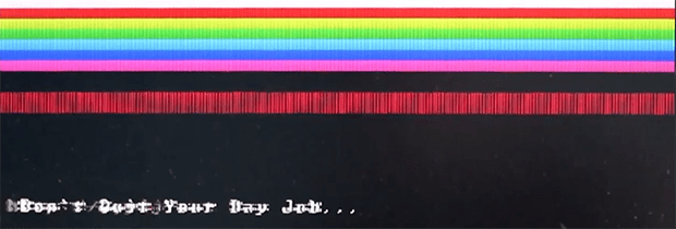
Good idea – I’ve gone back and added your suggested picture of color bars so you can count the transitions to verify it is more than 60. I put it in the demo section below the video and you can click it to zoom in.
I disagree on the font math, though. “Don’t Quit Your Day Job…” is 26 characters wide (including spaces). 16 pixel width characters means you’d need a minimum of 416 pixels to show the line, and you can see in the video it comes to a bit more than halfway across my screen. I don’t know how you can fit 26 characters in 60 pixels (even with the 8 pixel wide font it would still take 208 pixels), since most pixels would be dedicated to the spaces between the letters.
Nice job!
But you can easily overclock AVRs and VGA can handle 25MHz as well… And with double clock SPI there is a nice pixel clock signal for multiplexing the 2×4 bit color signal (it’s very time critical though: so you have to count instructions)
But the main problem is memory, if you want to do more than text with patterns. I used a ATMega644p/1284p with at least 4k RAM… Recently I built a video card with an old 256×16 DRAM chip and it achieved 800×600 with a 20MHz processor clock
Hi PK, I can not reply to your comment. Might be a limitation on HaD.
Thanks for the new picture. It shows maybe 25*8=200 pixels per line. This is around 8 million pixels per second with 3 bits pits per pixel. This is reasonable on an ATmega @16MHz processor clock (2 processor clock cycles per pixel). Your software might write 4 million bytes per second to the port (4 processor clock cycles per pixel).
Clocking the the external hardware at 32MHz does not make sense to me. I would run it at 8 MHz.
The textmode (or a monochrome mode) is a different story. It might use the UART or SPI. 16 million pixel per second (400 per line) might be possible without external hardware. But as far as I know, this will produce a gap after 8 pixels.