Way back in 2007, someone on a VW TDI forum came up with a new boost gauge project. At the time, it was a remarkable feat of engineering, capable of displaying the manifold pressure on a tiny OLED on the dashboard. No project has yet reached this caliber since. [Digital Corpus] is revisiting the project, making it his own, adding a few upgrades, and entering it into the Hackaday Prize.
The D-DAQ, as [Digital] calls his new project is using an absolute pressure sensor, unlike its predecessor. This gives the turbo gauge a much larger range than the original project, and also allows the D-DAQ to measure partial vacuum in non-diesel turbos.
In addition, the D-DAQ has a much wider scope than the original project, and as such will function as much more than a simple boost gauge. [Digital] sees the D-DAQ as being a complete performance monitor and logger, capable of tracking the exhaust gas temperature, battery voltage, and just about anything else with 10 analog pins. Data will be saved to a MicroSD card, and instead of a single display, the D-DAQ will feature three 160×128 OLEDs.
It’s certainly not what you’d expect from a Hackaday Prize entry, but with these features, it’s very possible the D-DAQ could be a successful product
![]() The project featured in this post is an entry in The Hackaday Prize. Build something awesome and win a trip to space or hundreds of other prizes.
The project featured in this post is an entry in The Hackaday Prize. Build something awesome and win a trip to space or hundreds of other prizes.


Let me get up off the porch for a second…
Ah, engine sensors! Can’t say enough about properly shielding your toys and filtering the inputs through RLC networks with zener protection. Automotive use is a pretty harsh environment, at least near the engine compartment.
I feel bad, last thursday I *just* sent a couple hundred 87c51 data logger pvbs to the dump that were specifically designed for automotive use. They were designed to read 8 egt, 8 cht, 2 tachs (you could guess what gear ratio was in use) and a bunch of 0-N (2.5,5,10) vfc a/d channels and 2 dac channels plus a pwm channel to control contrast on a LCD, … plus two strain gauge inputs for load cells. I also dumped three folders of documents about them that might have been useful to someone… Sorry, I never thought someone else would want that stuff.
I think I sold about 30 of them to Volvo, and maybe 85 in total. They were rs-232 and ran off 12vdc. Had some pretty software to drive a 160×128 LCD display. Then they became computer controlled digital scales (sold 6), a weather station, a talking weather station you could call by phone and then an EKG scanner (turns out a precision differential amplifier has a LOT of uses) that was kind of neat…
The hardest part was driving color printers directly from 8051 code to get 4 color graphic plots. It wasn’t that different from writing drivers for lcds, actually.
I was so proud of them at the time. I also dumped off all the fugly prototypes lovingly photo-etched using photo sensitized boards and drilled one hole at a time. The production boards were bright blue and yellow… I wish I could go back in time and take photos and scan the filter designs – they were all field tested and inexpensive to build. The only hard part was carefully matching resistors with a 5 digit DVM to get .1% accuracy from 1% resistors, but most people could get away with 1% for almost all the apps you see here.
I want to say this: You can do anything!
Thank you for the kind words. I’m new to doing something of this scale of complexity. I’m open to any tips and pointers other have for me with this. I’m new to hardware noise suppression so if you have any wise words on this I wouldn’t mind a push in the right direction. This week I start work on the sensor boards that will be residing in the engine bay. The main board will most likely be in the cabin; expecting it to reside in a dashboard.
I’d like to echo your last statement because it’s so true. You just need patience and willingness to make mistakes. As long as you persevere, anyone can do great things :)
Anyone with a passion, and access to the internet. Passion helps with the perseverance, and the internet helps with research, but isn’t completely necessary, just helpful.
+1 on noise suppression. Software can only go so far. I’d also strongly recommend against mounting a board under-hood, even in an enclosure. There’s a ton of environmental abuse that goes on in there. Most bays are open to the elements, and then there’s the heat cycling and everything else. We’ve killed a few relatively simple rev limiter setups from big companies by engine bay mounting them, put the newest one in the cabin and it’s happily working away, but this is on a racing application. Also- look into M12 cables/connections. Nice vibration, noise, and abrasion resistant properties and not a terrible price either, plus gives it a nice finished look. They’re used all over in the machine tool industry.
Supporting GM sensors will also appeal to a ton of people, good price point and well documented thanks to projects like ECM-link and Megasquirt.
Best of luck, I’m excited to see where this goes, and I just might be bugging you for a board ready to run at some point on the racecars (especially if it supports CAN- having something like that on my ’08 Mini cooper B-spec racer would be awesome!)
I’m aware of various Bosch boost/pressure sensors and have a channel or two to access them to characterize their outputs, but I’m not familiar with GM’s equivalents. I have an auxiliary, 3 wire sensor input as a 4th on-board dedicated input. I just need the parameters of it’s output and have that updated by user input or compiled into a database.
My power supply subsystem I’ve only spec’d for going up to 50˚C so engine bay was kinda out of the question. I’m running a diesel and so are any of the friend’s and family’s cars I can do testing with so the alternator is my current, primary noise source. I wish I had more access to a gas engine to see what a distributor and spark plugs do for EMI generation.
I want to simplify the display setup when I have a chance. Running a bunch of small conductors seems okay for now. However, if I switch over to a micro-to-micro scheme so that a salve uC is driving each display, easily larger than 128×160 too, then I can drop conductor count and change to different assemblies. I’ll keep those M12 setups bookmarked for when I do a major revision next. Thanks!
From experience:
The temp thing isn’t that big of a deal unless you want 100% reliability. You should really mount the sensor conditioning near the sensor, though – it makes a difference. Again, if you’re just driving pretty little raster gauges, errors won’t really matter. My stuff was for *science!* but I doubt I was better than ~1% on production units.
Also, look into conformal coatings – oh my gosh they made a difference. I used two. However, it also drops the odds of easy repair to almost zero – you have to unearth stuff. I used nylon multi-pin connectors and smc style stuff (screw on like they use for microwave and wifi radio) to get in and out, plus special thermocouple connectors.
Thermocouples require some thought, and you have to compensate for the junction from the thermocouple to whatever you’re using to get the signal to the a/d. Worse, anytime you change alloys, you just added another thermocouple. TC signals don’t change quickly, so this is the place to mux inputs to cut down on filtering parts count, and don’t forget to keep separate calibration factors for each channel, even if most of the processing happens after the mux.
You can use curve fitting to get excellent accuracy at higher resolutions by diving the signal input range into blocks and using a separate ax+y or ax3+y2+z curve fitter. However, at most engine heat ranges (both cht and egt) you can be within 2-4F and still call it good.
I just liked plus/minus 1F.
Filtering needs to be designed to block ignition noise, RF, electrical interference and the inexplicable pixie lightning that appears long enough to latch up a pin on your mcu or worse, blow a connecting wire inside your chip. Put zener diodes (or any similar technique) between your signal and the supply rails. Having higher quality op-amps that can go rail to rail helps a lot.
Get into the habit of using generic signal conditioning blocks, that is, have a go to ref design for a universal “protect/pre-filter/gain/offset/post-filter/protect” block with excellent fat fat fat ground planes and big well filtered power (with decoupling caps ftw) you can get really good at adding sensors. Signal gnd isn’t always ref gnd. Also, look into chokes and inductors if you haven’t already.
Also, for fast stuff, filters screw with timing – they add signal delay because of math and physics. This won’t matter that much in automotive stuff unless you’re doing ninja class ECU or diagnostics, but life is too short for that on street cars.
Side note: I remember talking to a group of pro engine-mechanics and feeling like I knew about transparent aluminum. Too bad patents are a messy minefield, as state of the art automotive diagnostics are a joke, and most auto mechanics are the equivalent of barbers with leeches. And don’t get me started on Porsche. They’re the GM of the exotic world.
Anyway – we expect great things, padawan!
Can someone explain why the use of curly traces in this or any pcb’s? Already saw those, don’t know why and where to use it.
It might help to clarify ‘curly’, but zigzags, jogs, squiggles etc are usually used to equalize lengths for high speed signals. If you look at your Computer’s PCB, by the memory and the processor, you will see a lot of squiggles and zigzags.
This is usually only used for multi-GHZ level signals, as different length traces can result in differing arrival times for bit information. With something like high speed DDR memory in a high performance desktop, signals that are not in sync can result in instability and data corruption.
Lenght matching/equalization, it seems to be an external DRAM/SDRAM, so all the clock, data and address lines should be the same length to ensure the ram sees the correct data, if you have different length traces you can have errors because the ram gets the clock earlier or later than the data and you get corrupted data.
No CAN interface to take a peek on the OEM sensors seems like a shortcoming.
I’ve learned that the trace length matching may not be required for accessing the 1Mbit SRAM, however I’ll be driving it around 65 MHz and from what I’ve read, I’m nipping on the threshold of possibly needing it. Due to the electrically noisy environment, I figure it couldn’t hurt.
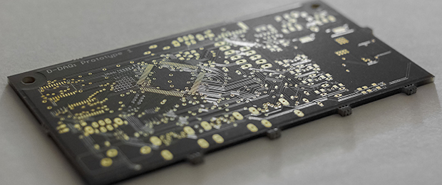
The board in the photo is my first prototype board. It has a few issues so I’m skipping past it. Both it and the 3rd prototype’s layout have a vertical Mini USB Type B port for the 2 lines related to CAN. Thankfully the PIC327XX series has 2 hardware CAN interfaces. I have a friend with a car new enough to sniff the CAN port, but I’m not sure when I’ll be able to functionally use the interface.
Slightly offtopic, but where did OP get the board in the picture made? That is an absolutely beautiful color scheme.
Not off topic, it’s okay. I actually was asked this over on the project page a couple hours ago, lol. Long story short, the lighting in the photo did have the spectra to show the Osh Park Purple solder mask so I did a selective color, i.e. black and white for all but 1 or 2 colors, conversion of the photos. I *had* to do some photography due to my background, Sorry for the confusion :)!
Something to be said for CAN sniffing. You can get practically free wifi/bluetooth CAN plugins from china. They either work or they don’t – they don’t do any signal conditioning. Thus you can connect to can using an optional module that can be unplugged.
For even less, you can get the same “ELM327” dongles with RS232 or RS485, which should be easier to interface a microcontroller with.
Thanks for the comments, made a lot of sense to me.
65MHz has a 15ns period. On PCB, signal can travel about 1 feet per 2 ns.
So your tracks would have to have skews of 1 feet (difference) before they are taking a significant chunk of your timing window (13%). Your data window is an order of magnitude too large to bother with this.
Two identical cases of people not knowing *when* to do track matching in the last few days, what are the chances? Don’t trust whatever your were reading when you can just analyze it like I did here.
I’ve read sources mentioning trace length matching when the length is anywhere from 1/20th the length of the propogation delay to 1/6th the length of the propogation delay. The first thing I did on the board layout was the MCU, the SRAM, and the pair of octal latches and that was back in January. Since I don’t have anything else over in that area of the PCB, I gain nor loose anything from making them all straight again so I’ve left them as is. The average length of a trace is about 1.1″ for those 16, btw.
I would say you would worry about signal integrity way before having to worry about skews between signals (e.g. data lines, diff pairs).
You are confusing terms in what you heard. Propagation delay only matter *in relationship* to how wide a data window you care about. If you skew is a large fraction of that, then you cut into the timing window. What it has vs other signals have absolutely no bearing unless there are chips that specifies some timing constraints for set up/ clock to data out constraints.
Signal integrity on the other hand matters…
When your propagation delay is more than 1/6 (or whatever magical number use by various rules of thumbs), then your track becomes a transmission line. (i.e. tracks too long vs the rise time you are dealing with) You would have to have impedance matching or some form of termination (series/parallel etc), or your signal quality would suffer.
When you have multiple outputs from a chip, then you have to start worrying about return paths, proper decoupling etc.
In ether case, a person who is aware of these thing would/should already know about managing signal skews, timing analyze etc.
I appreciate the explanations. In fact, your explanation about what makes something a transmission line is the only definition I’ve seem and I’ve been searching for that classification for a couple months. Transmission line theory, terminations, etc are a mess to read up on. Thank you.
I’m building D-DAQ for my own use, but more importantly, learning a little about a lot of different fields in electronics. I’m sure there are a bunch of things on it that can be improved or corrected :)
Might want to read up here: http://www.signalintegrity.com/Pubs/pubsKeyword.htm
Those usually points to his web articles and are of a light reading nature that talks about application and not just theory. Just that there are too many of them to do in one sitting.
He has publish a couple of books in the field as well as doing trainings. He is one school of thought. Just like the Kung Fu schools, there are various one that might do things different in this field.
Looking forward to the results from this project, especially if it talks OBDII!
This looks very similar to 14point7’s iDash, but hopefully much cheaper. The iDash is a similar datalogger but only outputs via its hosted HTML5 webpage over wifi.
I personally would prefer a simpler device with an integrated screen at a lower price, and I’m looking forward to finding out if the D-DAQ can become just that.
My apologies for a late reply.
Unfortunately, an integrated screen is not how D-DAQ has been designed. A pressure sensor and EGT sensor are the only 2 hardware integrated devices utilized, functionally speaking. Locking into 1 screen size, handling mounting of the device and scree, handling the heat from direct sunlight, is not something I’ve designed D-DAQ around.
Having the ability to attach different screens of different sizes and resolutions and be flexible through being modular have been priority design criteria. By trying to build theis project so it is electrically solid and using standard interconnects drives the price up a bit too. Right now for parts and boards alone in single quantity, it would cost a solid $180 to make a 3-head version of D-DAQ yourself.
Please keep in mind, iDash’s sample rate is not published and I cannot seem to find it online. I’m expecting D-DAQ to be able to perform at least 1 Ksps and if all works out, I’ll be raising this to 10-20 Ksps if I can.
Digital I would be interested to talk to you some more about your project. We have a small project that we could maybe compliment each other in operation… we handle ODBII/CAN with GPS, Video and telemetry.
Drop me a line and we can talk.
Your contact page does not seem to be working. Please feel free to email me at gmail with a period between the two words in my user name, lower case.