ATtiny84 Powered Minimalist LED Clock

LED Clock ATtiny84

We feature a lot of clock builds on HaD, and the reason is that they are cool. Even simple ones are cool. Not everyone can say they built a clock. [Chris] took a ride on the DIY Clock train and came up with this LED-based clock that is controlled by an ATtiny84 chip.

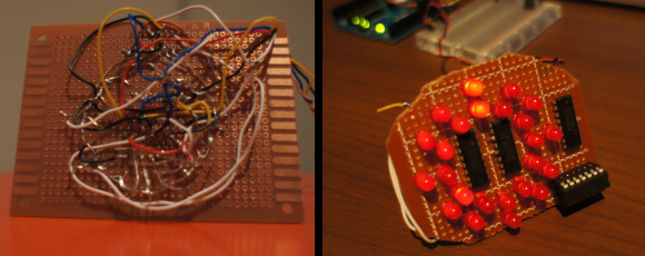
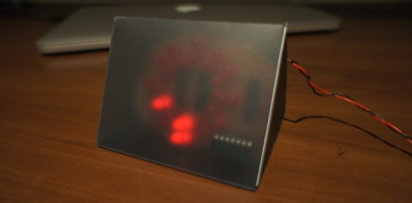
The clock has 24 LEDs total, 1 for each hour and 1 for every 5 minute increment. The 24 LEDs are arranged in 2 concentric rings. To display the hour, both LEDs at the same angle are lit up. To show the minutes, just the inner LED is lit. The main image above shows 6:40.

If you are familiar with the ATtiny84 you know that it only has 12 in/out pins, which is significantly less than the amount of LEDs that need controlling. [Chris] decided to use some 74HC595 shift registers to increase the IO pins on the ATtiny. The entire build is installed on a protoboard with quite a bit of point-to-point wiring. A simple tinted plastic case finishes the project and gives it a modern look.

[Chris] made the code for his clock available in case any readers are interested in making one.

LED Clock ATtiny84

Reflow Oven Controller With Graphic LCD

Reflow Controller

A reflow oven is one of the most useful tools you will ever have, and if you haven’t built one yet, now is as good a time as any. [0xPIT’s] Arduino based reflow oven controller with a graphic LCD is one of the nicest reflow controllers we’ve seen.

Having a reflow oven opens up a world of possibilities. All of those impossible to solder surface mount devices are now easier than ever. Built around the Arduino Pro Micro and an Adafruit TFT color LCD, this project is very straight forward. You can either make your own controller PCB, or use [0xPIT’s] design. His design is built around two solid state relays, one for the heating elements and one for the convection fan. “The software uses PID control of the heater and fan output for improved temperature stability.” The project write-up is also on github, so be sure to scroll down and take a look at the README.

All you need to do is build any of the laser cutters and pick and place machines that we have featured over the years, and you too can have a complete surface mount assembly line!

Heating Up A Printrbot’s Bed

A heated bed for the Printrbot 3D printer

Heated beds for 3D printers help reduce the amount of curling and warping of parts. The warping happens when the part cools and contracts. The heated bed keeps the part warm for the entire print and reduces the warping.

As an upgrade to her Printrbot, [Erin] added a heated bed. The first plan was to DIY one using Nichrome wire, but heated beds are available at low cost. They’re basically just a PCB with a long trace that acts as a resistor. She added a thermistor to monitor temperature and allow for accurate control.

The Printrbot heated bed worked, but didn’t heat up quite quick enough. [Erin] was quick to scratch off the solder mask and solder new leads onto the board. This converted the board into two parallel resistors, halving the resistance and doubling the power.

This version heated up very quickly, but didn’t have a steady heat. The simple control that was being used was insufficient, and a PID controller was needed. This type of control loop helps deal with problems such as oscillations.

The Printrbot’s firmware is based on Marlin, which has PID support disabled by default. After rebuilding the code and flashing, the PID gains could be adjusted using g-codes. With the values tuned, [Erin]’s printer was holding steady heat, and can now print ABS and PLA with minimal warping.

CY8CKIT-049-41XX Dev Kit

Cypress Launches $5 ARM Dev Board

We do love new development boards at Hackaday, and it’s always nice to see companies providing cheap tools for their products. For those needing a cheap ARM solution, Cypress has just released a PSoC based board that’ll cost you less than $5.

There’s two main ICs on the development board. The first is the target: an ARM Cortex M0+ based PSoC 4 MCU. The second is a CY7C65211 USB bridge. This device is communicates with the target’s built in bootloader for flashing code.

The bridge can also be configured to talk UART, GPIO, I2C or SPI.  If you need a USB to serial converter, this part of the board could be worth $5 alone.

The PSoC 4 target happens to be similar to the one our own [Bil Herd] used in his Introduction to PSoC video. If you’re looking to get into PSoC, [Bil] provides a good introduction to what makes these chips unique, and how to get started.

From 300W To 10W — A LED Lighting Solution

LED halogen light

Halogen lights are great — they produce lots of bright warm light, but they suck a lot of juice to run. [Sven] had found a nice floor lamp years ago that was in pretty rough shape — his wife redecorated it, and he fixed it up, but between the 300W power consumption and the lack of a dimmer circuit (this thing was bright!), he knew he had to upgrade.

Like we recommend for all projects, [Sven] started by setting some goals for the conversion. He wanted to keep the warm light color tone, produce over 700lm, allow for dimming via remote, and work with presence detection.

He sourced a 10W power LED which requires 12V @950mA to run, which almost stumped him as it turns out there aren’t many LED drivers of that specification even available! Luckily, he managed to find one from China that wasn’t too large and would fit in the lamp cover with the other components. He found a large heat sink for the LED, and for safety, has even wired it up with a temperature sensor to his Arduino in order to shut it down if it gets too hot. The Arduino also provides the dimming circuit and remote control capabilities.

[Sven] admits that the end result isn’t that pretty, but lucky for him, it stands about 6′ tall so no one can see the jumble of wires and components inside! This is also only the first iteration, as he plans on upgrading it further — as it turns out, 700lm isn’t quite enough.

THP Entry: Digital Gauges For Everything Automotive

DDAQ

Way back in 2007, someone on a VW TDI forum came up with a new boost gauge project. At the time, it was a remarkable feat of engineering, capable of displaying the manifold pressure on a tiny OLED on the dashboard. No project has yet reached this caliber since. [Digital Corpus] is revisiting the project, making it his own, adding a few upgrades, and entering it into the Hackaday Prize.

The D-DAQ, as [Digital] calls his new project is using an absolute pressure sensor, unlike its predecessor. This gives the turbo gauge a much larger range than the original project, and also allows the D-DAQ to measure partial vacuum in non-diesel turbos.

In addition, the D-DAQ has a much wider scope than the original project, and as such will function as much more than a simple boost gauge. [Digital] sees the D-DAQ as being a complete performance monitor and logger, capable of tracking the exhaust gas temperature, battery voltage, and just about anything else with 10 analog pins. Data will be saved to a MicroSD card, and instead of a single display, the D-DAQ will feature three 160×128 OLEDs.

It’s certainly not what you’d expect from a Hackaday Prize entry, but with these features, it’s very possible the D-DAQ could be a successful product


SpaceWrencherThe project featured in this post is an entry in The Hackaday Prize. Build something awesome and win a trip to space or hundreds of other prizes.

The Rotary Cell Phone

It’s happened. It’s finally happened. In a move that has hipsters donning their good flannel and breaking out that case of Genesee they were saving for a special occasion, the rotary cell phone is now a reality.

[Jaromir] created this astonishingly retro future device as an entry for the NXP LPC810 challenge, a contest to do the most with an ARM Cortex M0+ microcontroller in an 8-pin package. Having only six I/O pins for controlling a GSM module, display a few buttons, and the fancy rotary dial meant [Jaromir] needed to expand his I/O some way. He chose a shift register to handle the buttons and display in a somewhat impressive demonstration of using a shift register as both an input and output expander at the same time.

From the videos [Jaromir] uploaded, the rotary cell phone isn’t ready for Think Geek to do a production run quite yet. He needs to enter the PIN for the SIM card, AT commands for the GSM module, and is, of course, a horrible method of user input for the younglings who have only seen rotary phones in old movies. That being said, it’s a rotary cell phone running on an 8-pin microcontroller. What more do you want?

Videos of this awesome this truly awesome phone in action below. If you’d like to build your own – and why wouldn’t you – all the files are available on [Jaromir]’s git

Continue reading “The Rotary Cell Phone”