If you want to program an AVR chip as inexpensively as possible, then [Ian’s] solution might just be for you. He built an AVR programmer using only four components. This design is based on the vusbtiny AVR programmer design, with a few components left out.
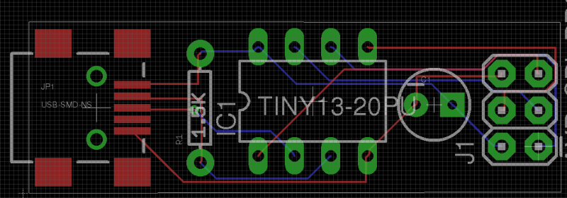
[Ian’s] design leaves out two of the resistors and two diodes, leaving just four components. These include a 1.5k resistor, a small capacitor, a USB connector, a six pin header, and an ATtiny45. He admits that this may not be exactly up to USB spec, but it does work.
This is one of those projects that is really an exercise in “will it work?” more than anything else. The fact that you need to first program an AVR chip means that this wouldn’t be useful in a pinch, because you would already have to have a working programmer. Nonetheless, it’s always fun to see what can be done with as little as possible.


Bad idea to use 5V signals for V-USB as USB signaling is 3.6V max.
What might not blows up one computer might not safe for another. What is cheap for your dongle would not be cheap if you blows up your hub or your PC’s USB port.
Well a simple fix is to just slap a zener diode and a small resistors on there. Easy enough to do on SMD without increasing the size of the board.
Which is exactly what he has left out from the original V-USB design. That one uses two clamping zeners on D+ and D- lines. Really don’t understand why these were left out here.
Hey, its me the author. My goal was to see how cheap I could make it, with or without complying to safety requirements :D. I agree, you need those diodes for proper operation, or you could use a resistor or 2 to voltage regulate the 5 to 3.3v. Or, god forbid, I could have spent the $0.50 for a voltage regulator! :)
IIRC USB ports should be able to handle Vbus+0.5V without getting damaged. The link is not required to work, but the port should not break. This is to prevent a USB cable with a broken ground connection from damaging the ports.
Nonetheless you should run the AVR from 3.3V. Using a zener can give signal integrity problems.
Running the AVR from a zener will likely cause problems in this case, because he needs 5V TTL levels on the output (it is a programmer, remember?).
The clamping zeners are not ideal, but but V-USB has much larger issues than this. Moreover, it is low speed USB only, so it should be manageable.
And the Vbus+0.5V tolerance – yes, that is in the spec. Unfortunately there are tons of poorly made hubs around that don’t have inputs protected properly and this will fry them.
I can confirm that this design won’t work no all computers. Actually, it only works like this on 1 of the 4 machines that I have at home.
ATmega32 define VIH: 0.6 * Vcc (min) and Vcc + 0.6V (max) for Vcc = 2.7V-5.5V. 5.5V * 0.6 = 3.3V (logic high minimum value). Since the inputs have less than 1uA leakage, most drivers should be fairly close to rail to rail outputs. In real life, the threshold is quite a bit lower.
A programmer that produces 3.3V VOH at its output along with a 100 ohms range series resistor (for current limiting as well as series damping) would be able to program AVR within that entire range. On the other hand, a 5V powered one would be over the Vcc+0.6V. You only need to clamp the MISO signal coming back from your target.
The zeners seem to work pretty well since thousands of Chinese USBasps use them.
Though I agree that 3.3V is preferred. A cheap and easy solution is a 1.7V red LED in series with Vbus. It doubles as a power LED. They also work as a fuse – draw more than 50mA, then poof!
I use these ones in a lot of my projects:
http://www.dipmicro.com/store/BR5379K
The problem is that VBUS is not guaranteed to be 5V and there are lots of drops along the way and get worse if there are heavy loads.
Again from the USB 2.0 spec:
• The voltage supplied by high-powered hub ports is 4.75 V to 5.25 V.
• The voltage supplied by low-powered hub ports is 4.4 V to 5.25 V.
• Bus-powered hubs can have a maximum drop of 350 mV from their cable plug (where they attach to a source of power) to their output port connectors (where they supply power).
• The maximum voltage drop (for detachable cables) between the A-series plug and B-series plug on VBUS is 125 mV (VBUSD).
• The maximum voltage drop for all cables between upstream and downstream on GND is 125 mV (VGNDD).
It’s not a problem for an Avr programmer. The tiny13 and a target AVR would do fine with 10mA @3.3V. Even at 20mA, it’s a long way from a “heavy load”.
I’ve measured power on many USB ports on desktop computers & laptops, and rarely see anything outside 5.0 – 5.05V. From a couple of dollar-store low-power hubs I get 4.9V.
So while you can get 5V right at the computer side, things are different at the hubs. Cheap Chinese hubs skips the diode and PTC because of cost, so they probably have lower drops. Don’t follow the specs, then your “design” would work only in your setup.
My hubs measured 4.7V and as low as 4.4V. These are the ones that put in a schottky diode in series to the Vbus, so that power don’t feed back on the upstream. Some have over current protection via PTC etc. So YMMV.
I suppose that is why similar projects that use only attiny, tend to use zener diodes on the data lines?
FYI: original USB specs (usb_20_012314) recommended a short circuit to VBUS to 5.25V. (Certainly not VBUS+0.5V). This has since been removed by “5V Short Circuit Withstand ECN”.
>Applies to: Universal Serial Bus Specification, Revision 2.0
>1. The 5V short circuit requirement limits the scalability of silicon fabrication processes moving forward. The advanced processes do not easily support this voltage level, which is 5X or more of the native process voltage.
>2. The proposed change also provides an opportunity in reducing the silicon area and average power. Analysis shows a ~16% transceiver silicon area reduction and a ~3x standby idle power saving can be achieved on a silicon process which does not support a 3.3 volt tolerant transistor.
>3. The original intent of this requirement was to protect the ports against degradation if the USB
cable was damaged resulting in a VBUS short to only to one or both of the data signal lines (Dp or Dm). Research into the likelihood of this condition occurring has resulted in zero reports of this fail condition. (Source: USB IF database)
>Change section 7.1.1 USB Driver Characteristic, 6 th paragraph as follows:
>A USB transceiver is recommended, but not required, to withstand a continuous short of D+ and/or D- to VBUS for a minimum of 24 hours without degradation.
uh strictly more complicated than the standard arduino programmer http://www.arduino.cc/en/Hacking/ParallelProgrammer?from=Main.ParallelProgrammer
I suppose it is valid for programming on the go (since thin and lights dont have parallel ports anymore), but at that point why not just burn a bootloader (takes 1k of flash, and 0 other resources)
no motherboard i’ve bought in the past 10 years has had a parallel port, so its pretty reasonable to omit parallel programmers at this point. The one and only time I built a parallel programmer was when i was a broke undergrad at home for the summer, with a bit of free time and access to my parents’ old computers
I use usbasp for long time now – so someone tell me, aside change of processor, and neglecting few components, what is the big difference?
Btw. best wishes for author of Usbaps Thomas Fischl
Hey, its the author:
Big differences:
1- This is pretty unsafe
2 – It uses usbtinyisp protocol, which I’ve had better luck with
3 – Uses internal clock source, so less stable
4 – Cheaper, unless you happen to be a factory in china. I don’t think we can ever compete with those 2$ usbasps on ebay
I’m not even sure if 4 is true.
At a reasonable quantity (I usually order atmel chips in 5-10-20 pieces from ebay) a tiny85 is around $2 per piece (attiny45 might be a bit cheaper). An atmega8 (or 8A or 88) is around 80-90 cents. The parts you’ve left out are really cheap, an SMD zener is around 2 cents/piece, a resistor is almost nothing. A crystal is around 7-10 cents, the caps for the crystal are almost free. You’ll need a slightly bigger PCB though.
Those traces seem kinda thin to me…
Yeah and that via is way too close to that trace
zener’s are cheapest and simple solution to make data lines in specs of usb specification, works for most pc just fine, have not fine one pc that have not accept the zener solution. Without zener’s most pc will reject the usb, not all pc’s, some will still work with 5v on the data lines.
Hm. I smell a competition coming- who wants to build the smallest AVR programmer?
If somebody else wants to challenge me on this, i’d be happy to keep this going! First, I’d remove the cap. Second, I’d use an smd QFN processor. Third, I’d use an arm with true analog outputs to emulate a resistor pulled up to five volts! I mean, smallest, not cheapest, right??? :D
Same thing with an attiny13 would be perfect !
Needs a 100nF decoupling cap.
Those electrolitics dont do well at high frequencies.
I’d go with a 0805 100nF cap. Cheap (<1c) and big enough to easily hand solder.
You could put the decoupling cap on the chip to save some PCB space.
http://nerdralph.blogspot.ca/2014/09/on-chip-decoupling-capacitors.html
Given that it's not driving any low-impedance lines (USB D+ & D- have 15-22K to ground), it might even work fine without a decoupling cap.
It is not static DC load that’s the issue. Most people here seem not to taken AC or parasitics into account even when the subject is about signal integrity.
When you drive a capacitive load e.g. long cables, or other chips, their capacitors no matter how small, needs to be charged going to logic high (or discharging to ground). Looking at a power supply impedance (once again, it is AC impedance), you want something locally that can supply that burst of current instead of the large impedance (inductance) coming down the cable.
Ideally, a good practice would use 3 capacitors for EMC reasons/signal quality. The power/ground routing is too thin, so introduces a lot of inductance. One at the connector for a return path for the signals. One across the microcontroller power/ground pin with thick and short track (or better still planes) and one at the output connector – once again help with the return paths. Smaller loop are means less EMC.
Kinda also neglects that you need an avr flasher to get this kit working… So you need a working one to build another working one.
Ugh… That trackwork… Why man?
You’ve got plenty of room and most of your components are through-hole… Widen your traces, remove 90degree bends, increase trace-to-trace and trace-to-pad clearances, add a ground plane. A couple of 100nF monolythic decouplers won’t hurt either
It looks like it’s been auto-routed currently
That’s because it was!
Simply replace the zeners with white LEDs so that the system can remain at 5V. There was a project at Sparkfun that made use of this for a V-USB keyboard. It was an ATTiny45/85 datalogger.
Do you have the source for that projec?. It sounds quite interesting.
https://www.sparkfun.com/products/9147
It’s called “Avr stick”, product ID : DEV-09147
OP website has been hackdotted; have a Google cache link http://webcache.googleusercontent.com/search?q=cache:k4uBesiCSBoJ:fobit.blogspot.com/2014/11/tiny-tiny-avr-programmer.html+&cd=1&hl=en&ct=clnk&gl=uk&client=firefox-a
This design is the most horrible I have seen for a very long time. Well, calling it a “design” is unfair. What is it doing on Hackaday anyway?
If you are proudly designing something that ugly you can skip the capacitor (target has some if it’s not yours) and the pull-up resistor (use MCU internal 20k pull-ups as voltage levels are overdriven and it will produce just enough level for attachment signalling) and it will still “work.”
The avr pullups are closer to 40k, so it is unlikely to work. You’d get less than 1.5v with 40k/15k.