
When choosing a low-level language, it’s hard to beat the efficiency of Forth while also maintaining some amount of readability. There are open source options for the language which makes it accessible, and it maintains its prevalence in astronomical and other embedded systems for its direct hardware control and streamlined use of limited resources even though the language started over 50 years ago. Unlike 50 years ago, though, you can now take your own self-contained Forth programmer on the go with you.
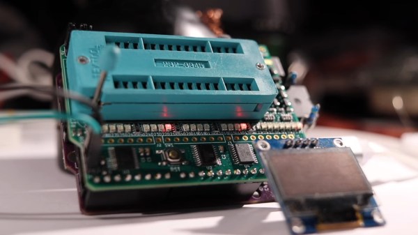
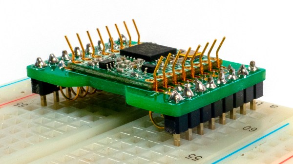
The small computer is built on a design that [Dennis] built a while back called my4TH which has its own dedicated 8-bit CPU and can store data in a 256 kB EEPROM chip. Everything else needed for the computer is built in as well but that original design didn’t include a few features that this one adds, most notably a small 40×4 character LCD and a keyboard. The build also adds a case to tie everything together, with ports on the back for I2C and power plus an RS232 port. An optional battery circuit lets the computer power up without an external power supply as well.
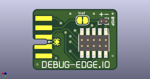
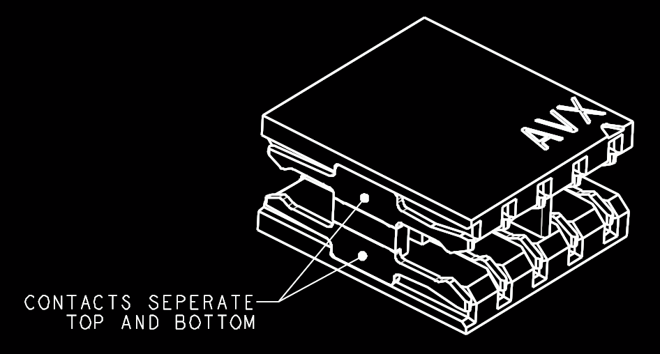 The name “Debug Edge” says it all. It’s a debug, edge connector. A connector for the edge of a PCBA to break out debug signals. Card edge connectors are nothing new but they typically either slot one PCBA perpendicularly into another (as in a PCI card) or hold them in parallel (as in a mini PCIe card or an m.2 SSD). The DebugEdge connector is more like a PCBA butt splice.


