RTL-SDR, the USB TV tuner turned software-defined radio is an amazing device, capable of listening to nearly anything from 25MHz to 1750MHz, fits in your pocket, and costs about $20. Even more astonishing is that it’s also a kinda-okay spectrum analyzer. [Kerry D. Wong] tested out one of these USB TV tuner, and the results are exactly what you would expect: it lacks a little precision, and sampling bandwidth is only a tiny bit terrible, but it does work.
A stock USB TV tuner doesn’t come with a connector that would normally be used for spectrum analysis. A BNC connector can be easily attached, as can a terminator to match the 75Ω impedance of the SDR. This isn’t really necessary; the frequencies being measured are low enough that you can get away without one.
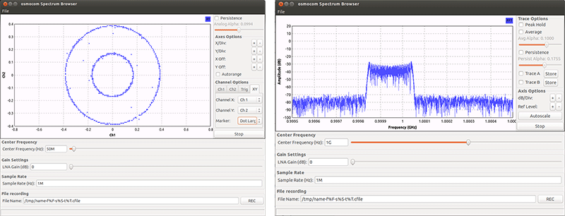
As far as software goes, [Kerry] first pulled out the usual suspects of the SDR world; rtlsdr-scanner distorted the measured spectrum, as did a lot of other SDR receivers. Gqrx SDR was the first one that worked well, but the king of this repurposing of USB TV tuners was OSMOCOM. There’s a huge number of tools for spectrum analysis right out of the box with this package.
How did the RTL SDR fare as a spectrum analyzer? Feeding some stuff in from a signal generator, [Kerry] discovered the LO in the RTL SDR was off by a hair. Also, OSMOCOM only measures amplitude in dB, not the dBm found in every other spectrum analyzer ever made. By measuring a 0 dBm signal whatever value displayed can be shifted up or down.
So, does it work? Yes, it does. If, for some reason, you need a spectrum analyzer now, can you use this? Yep. Pretty cool.


you just wanted to listen to tetra devices, admit it ;D
Tetra? You mean the unencrypted one ? Who uses unencrypted TETRA anyways ?
You would be surprised how many countries use it. Police mostly which is shocking :)
Since when is TETRA unencrypted?
Not fully as I remember it. And in some countries not at all.
Me and a friend recently used an RTLSDR while tuning the drive levels and filters on a CB radio to make sure it was transmitting with nice clean modulation. Came in very handy.
Wow! A CB user concerned about clean transmitting! You are one in a billion!
Ha! Oh that’s the truth. Could not believe the utter garbage I was hearing awhile back on a CB band, but it was too funny to stop listening!
I’ve been using my RTL-SDRs as band scopes (basically a low-budget spectrum analyzer often used in ham radio to view signals across entire bands) for some time now. In fact, it was a post on QRZ.com about using them as spectrum analyzers that led me to them in the first place.
http://forums.qrz.com/showthread.php?391657-RTL-2832u-R820T-SDR-as-a-Spectrum-Analyser
Nice link, funny someone was asking “where’s sue?” lol, she’s pretty active on qrz forums.
I plan on using mine for a mobile spectrum analyzer, just wish phones had 2 USB-otg ports as getting charge and data is a little tricky. Someone made a cable but not sure about resistance value to use.
> capable of listening to nearly anything from 25MHz to 1750MHz
> the frequencies being measured are low enough that you can get away without one.
If 1750MHz is not considered as high enough frequency? At what frequency do you start putting on proper connectors and terminations?
BTW the original article has connectors and terminators. Just that it is not using the right type of terminations. No where in the article said about “A BNC connector can be easily attached, as can a terminator to match the 75Ω impedance of the SDR. This isn’t really necessary; the frequencies being measured are low enough that you can get away without one.”
This is what the article said:
>Note that the input impedance of the SDR is typically 75Ω, ideally you should use a 75Ω to 50Ω feedthrough termination adapter to ensure proper impedance matching. But since the frequency range of the SDR is not particularly high, the added SWR is low enough and typically not a big concern.
>The signal to be analyzed comes in from the the BNC cable on the left and goes through a BNC Tee, one side of the Tee is terminated with a 50Ω load and the other side goes through a BNC-MCX converter and then goes to the SDR. Of course you can always use a feedthrough terminator instead of the Tee. Again, because the frequency range is relatively low, even without proper termination, the signal fluctuation across the measurable spectrum due to reflection is small enough for casual measurements.
I “might” have a 50 ohm feedthrough terminator, I doubt I have a 50 to 75 ohm balun. I’ll check TAS (That Auction Site)
$20 is a bit much for a rtl sdr dongle. I paid $11 for mine on Aliexpress several months ago. Well worth the money.
I I did $7 :D
Don’t forget the direct sampling mod, should you need to work on the lower HF or want to use external front ends and filters which could be the case in a spectrum analyzer.
http://superkuh.com/rtlsdr.html#directsample
At http://sdr.osmocom.org/trac/wiki/fosphor there is a spectrum analyser which is much more advanced. On my RTL-SRD however it does an odd kind of uneven binning pattern. If anyone knows what’s the matter, please advise.
BTW, with the AMD proprietary GPU driver, I needed to tell the compiler where the OpenGL libraries were located, and again on run-time, with “export LD_LIBRARY_PATH=/usr/lib/fglrx”.
can you post a screenie?
Certainly: http://imgur.com/8Q6b9Pe
Hah! Solved it! I used gnuradio-companion to create flowchart, and on the osmocom Source block I set Ch0 Frequency to 288e5. 100e6 caused that strange binning issue. Device arguments: rtl_tcp=127.0.0.1:1234. rtl_tcp needs of course to be running.
I love gr-fosphor. It looks so nice you can’t really capture the detail in screenshots or encoded video. I use the gr-phosphor module to display the output of the gnu radio application multimode. The best part about GNU Radio is that this literally only took a handful of clicks and connecting blocks. Here’s a video of using it with an rtlsdr dongle, https://www.youtube.com/watch?v=wNVWYgpR5XI
Is this meant to be 16APSK with out frequency correction? Hence the rotation of the constellation. It looks like there is very little noise.
people are finding the SDRplay RSP works well using Spectrum Lab software from http://www.qsl.net/dl4yhf/spectra1.html
i’m just looking for a software that can be downloaded, installed and work in XP 32bit as a spectrum analyzer,
why is it so hard to do..