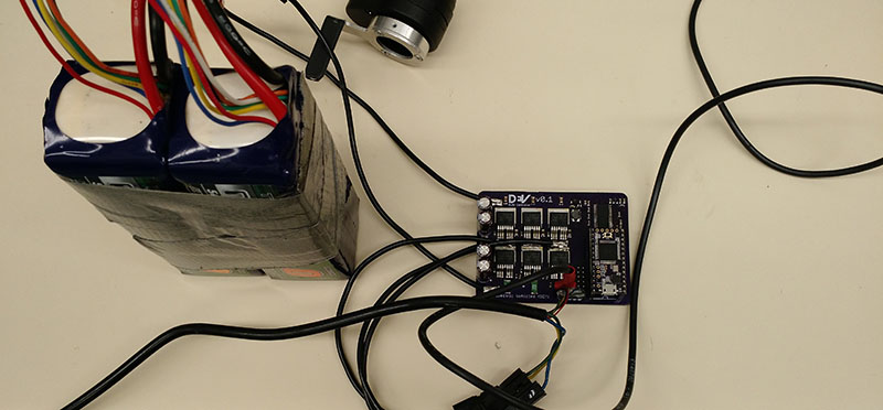
[Will] is on the electric vehicle team at Duke, and this year they’re trying to finally beat a high school team. This year they’re going all out with a monocoque carbon fiber body, and since [Will] is on the electronics team, he’s trying his best by building a new brushless DC motor controller.
Last year, a rule change required the Duke team to build a custom controller, and this time around they’re refining their earlier controller by making it smaller and putting a more beginner-friendly microcontroller on board. Last years used an STM32, but this time around they’re using a Teensy 3.1. The driver itself is a TI DRV8301, a somewhat magical 3 phase 2A gate driver.
The most efficient strategy of driving a motor is to pulse the throttle a little bit and coast the rest of the time. It’s the strategy most of the other teams in the competition use, but this driver is over-engineered by a large margin. [Will] put up a video of the motor controller in action, you can check that out below.


Those damn high schoolers…
What is that kind of a throttle input? What are they called?
Not sure what you’re asking. Thumb throttle?
If it’s made for an ebike, it’s probably a hall-sensor output, but potentiometer output is also available for that purpose (although uncommon to the point of rarity).
Thank you. Thumb Throttle brought up some products on ebay that are in that manner. I’ts sometimes a struggle looking for certain items hen your native language is not English. I often spend time typing in words like “finger throttle”, “handlebar throttle”, “throttle encoder ring”… so yeah, thank you.
The one I have on there in the video is a resistive thumb throttle. It only has two terminals (the leads of the resistor), and I have another resistor soldered under the heat shrink to act as a voltage divider.
Thanks to you as well.
2A rating MOSFET gate drivers sound kind of low for those MOSFET as they have huge gate capacitance (probably in the tens of thousands of pF if not more) to charge and discharge quickly each time you turn them on/off. I*dt=C*V The gate driver datasheet should state the gate capacitance that it can drive and that should match the gate capacitance (or gate charge) of the MOSFET in its datasheet.
The routing of the gate signals aren’t good – you really need to pay attention of the return path. When you are charging/discharging those gate capacitance, a equal and opposite amount of current returns to the driver chip via the ground. You want to minimize the loop area of those high current path by having those high speed/high current (2A or more) directly on top of a non-slotted ground fill between the MOSFET all the way to the power ground of the gate driver.
The throttle is probably non-linear because throttles usually control power, not speed.
The resistance of this particular throttle doesn’t increase linearly with angle regardless of its application. And the throttle commands torque in this system.
Thanks for the comment tekkieneet, I appreciate the feedback.
According to the datasheet for the MOSFETs the input capacitance is 9200 pF. I considered that this was maybe too high when I was selecting the MOSFETS, but I couldn’t find any value on the DRV8301 datasheet which stated the capacitance it could drive. Shane Colton (http://scolton.blogspot.com/search/label/FF) used these MOSFETS with the DRV8301 and has done all sorts of complicated sensorless stuff, so I figured I would be alright. I’ve used a scope to measure the gate charge/discharge time, and it was around 50 ns. This matches roughly the value given by the q=CV equation you gave. I’m going to use smaller MOSFETs in the next version of my controller anyway because 30A continuous is way overkill for the competition we’re in.
As for the routing of the gate signals, good point. I’ll pay more attention to this next time.
You can also use smaller dual gate drivers and locate them next to the MOSFET. That should help to improve the routing and keep those gate drivers signal short and wide. I would still route the signals (including the input to the gate drivers) as if they are high speed controlled impedance lines.
TI also has some fancy H bridge drivers (for PWM) that manages timing for shoot through such as adaptive dead time. e.g. TPS28226 (High-Frequency 4-A Sink Synchronous MOSFET Drivers) Read up on their explanation, layout section (even if you aren’t using this chip). There are lot of good material there on this and similar chips.
You’d want to find a balance between how much power is used to do the switching, lost during the switching and lost in on-resistance. Bigger faster isn’t always better
Since it is digital PWM, the frequency isn’t going to be that high vs a switch mode supply at a few hundred kHz. The amount of switching losses per transition while high for large MOSFET, at low frequency. In the end, conduction losses might still dominate. It is worth looking at the numbers.
If the goal of the competition is total power efficiency, you’re going to need to ditch trapezoidal commutation ASAP. For efficiency you need to use true sinusoidal PWM-based control. From an electronics standpoint that means optimizing the MOSFETs for gate charge vs PWM frequency in order to keep the controller’s power dissipation under control.
However I think the key differentiation you’d get with proper sinusoidal control would be actual control over the motor power levels. Once you have the required PWM control over the motor’s coil drive, you can simply scale the sin() output values, which results in commutation continuing at that reduced power level. You should be able to run indefinitely at these reduced levels, which seems to me would be *significantly* more efficient than pulsing the throttle.
I’m already working on sinusoidal commutation. At some point I’d like to perform a formal test of the pulse-coast tactic vs. other strategies.
pulsing works on a combustion engines because they are more efficient under load, but I don’t see that working on electric.
I think you’d want to drive the motor and look at the back emf to determine what waveforms to use, generally the distinction between synchronous PM-AC and brush-less DC, is whether they a made to have sinusoidal or trapezoidal EMF
For user friendly, keep your STM and install MicroPython.
Hi,
Do you share consideration of BLDC controller program because I liked your project :)