Adding A Third Wheel (And Speed Boost) To An Electric Scooter

The story of how [Tony]’s three-wheeled electric scooter came to be has a beginning that may sound familiar. One day, he was browsing overseas resellers and came across a new part, followed immediately by a visit from the Good Ideas Fairy. That’s what led him to upgrade his DIY electric scooter to three wheels last year, giving it a nice speed boost in the process!

The part [Tony] ran across was a dual brushless drive unit for motorizing a mountain board. Mountain boards are a type of off-road skateboard, and this unit provided two powered wheels in a single handy package. [Tony] ended up removing the rear wheel from his electric scooter and replacing it with the powered mountain board assembly.

He also made his own Arduino-based interface to the controller that provides separate throttle and braking inputs, because the traditional twist-throttle of a scooter wasn’t really keeping up with what the new (and more powerful) scooter could do. After wiring everything up with a battery, the three-wheeled electric scooter was born. It’s even got headlights!

[Tony]’s no stranger to making his own electric scooters, and the fact that parts are easily available puts this kind of vehicular experimentation into nearly anybody’s hands. So if you’re finding yourself inspired, why not order some stuff, bolt that stuff together, and go for a ride where the only limitation is personal courage?

How Far Can You Push A £500 Small Electric Car; Four Years Of The Hacky Racer

Four years ago when the idea of a pandemic was something which only worried a few epidemiologists, a group of British hardware hackers and robotic combat enthusiasts came up with an idea. They would take inspiration from the American Power Racing Series to create their own small electric racing formula. Hacky Racers became a rougher version of its transatlantic cousin racing on mixed surfaces rather than tarmac, and as an inaugural meeting that first group of racers convened on a cider farm in Somerset to give it a try. Last weekend they were back at the same farm after four years of Hacky Racer development with racing having been interrupted by the pandemic, and Hackaday came along once more to see how the cars had evolved. Continue reading “How Far Can You Push A £500 Small Electric Car; Four Years Of The Hacky Racer”

Ball Balancing Wheel Puts A Spin On Inverted Pendulums

If you march sufficiently deep into the wilderness of control theory, you’ll no doubt encounter the inverted pendulum problem. These balancing acts have emerged with a number of variants over the years, but just because it’s been done before doesn’t mean there’s no space for something new. Here, [David Gonzalez], has taken this classic problem and given it an original own spin–literally–where the balancing act is now a ball balanced precariously upon a spinning wheel. (Video, embedded below.) Mix in a little computer vision for sensing, a dash of brushless motor control, a bit of math, and you have yourself a closed-loop system that’s bound to turn a few heads.

[David’s] implementation is a healthy mix of classic control theory with some modern electronics. From the theory bucket, there’s a state-space controller to drive both the angle and angular velocity of the ball to zero. The “state” is a combination of four terms: the ball angle, the ball’s angular velocity, the wheel angle, and the wheel’s angular velocity. [David] weights each of these terms and sums them together to create an input value to adjust the motor velocity driving the wheel and balance the ball.

From the electronics bin, [David] opted for an ESP32 running Arduino, the custom Janus Brushless Motor Controller running SimpleFOC, and a Maix Bit Microcontroller with an added camera running MicroPython to compute the ball angle. Finally, if you’re curious to dig into the source code, [David] has kindly posted the firmware on Github.

We love seeing folks mix a bit of control theory into an amalgamation of familiar electronics. And as both precision sensors and motor controllers continue to improve, we’re excited to see how the landscape of projects changes yet again. Hungry for more folks closing the loop on unstable systems? Look no further than [UFactory’s] ball balancing robot and [Gear Down for What’s] two wheeled speedster.

Continue reading “Ball Balancing Wheel Puts A Spin On Inverted Pendulums”

Tiny PCB Motor Robot Is Making Its First Wobbly Moves

[Carl Bugeja] has been working on his PCB motors for more than three years now, and it doesn’t seem like he is close to running out of ideas for the project. His latest creation is a tiny Bluetooth-controlled robot built around two of these motors.

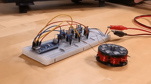
One of the main challenges of these axial flux PCB motors is their low torque output, so [Carl] had to make the robot as light as possible. The main board contains a microcontroller module with integrated Bluetooth, an IMU, regulator, and two motor drivers. The motor stator boards are soldered to the main board using 90° header pins. The frame for the body and the rotors for the motors are 3D printed. A set of four neodymium magnets and a bearing is press-fit into each rotor. The motor shafts are off-the-shelf PCB pins with one end soldered to the stator board. Power comes from a small single-cell lipo battery attached to the main board.

The robot moves, but with a jerking motion, and keeps making unintended turns. The primary cause of this seems to be the wobbly rotors, which mean that the output torque fluctuates throughout the rotation of the motor. Since there are only two points of contact to the ground, only the weight of the board and battery is preventing the central part from rotating with the motors. This doesn’t look like it’s quite enough, so [Carl] wants to experiment with using the IMU to smooth out the motion. For the next version, he’s also working on a new shaft mount, a metal rotor, and a more efficient motor design.

We look forward to seeing this in action, and also what other application [Carl] can come up with. He has already experimented with turning it into a stepper motor, a linear motor, and a tiny jigsaw motor.

Continue reading “Tiny PCB Motor Robot Is Making Its First Wobbly Moves”

The Dynamotor Simplified

[Robert Murray-Smith] doesn’t like the price of inverters to convert DC to AC. That led him to build a dynamotor, or what is sometimes called a motor-generator set. These devices are just DC motors driving a generator. Of course, motors can also be used as generators and [Robert] had a stack of brushless motors in the form of PC fans. A two-fan dynamotor was born.

The brushless motors are attractive because, traditionally, the brushes are what usually fail on a dynamotor. The fan that will act as a generator needs some surgery, but it is simple. He scraped off all the control electronics and connected wires to the coils to form a three-phase generator. There’s no need for the fan blades in that configuration, either. If you were using ordinary motors and a generator, getting shafts concentric would be an important task. With the fans, it is simple to just line up the mounting holes and you get perfect alignment for free.

How does it work? [Robert] has a second video showing the output on a scope. You can see both videos below. The dynamotor makes a good-looking sine wave, probably much better than most reasonable-priced solid state inverters. He didn’t mention how much current he could successfully draw, but it probably isn’t much. You’d also need a transformer to replace a commercial inverter that would put out line voltage, so that would be some more loos in the system. On the other hand, if you wanted AC at a lower voltage, you might just replace all the transformers, if you were building a piece of gear yourself.

We’ve looked at how these things work in some detail. There were common in old tube radios, particularly military ones.

Continue reading “The Dynamotor Simplified”

Shredding The Ice With Powered Skates

The availability of small and powerful brushless motors has been instrumental in the development of so-called micro-mobility vehicles. But if your commute involves crossing a frozen lake, you might find the options a bit lacking. Fortunately [Simon] from [RCLifeOn] now has a solution for you in the form of motorized ice skates.

[Simon] used 3D printed brackets to mount outrunner brushless motors to the back of a pair of ice-skates. The spinning outer housing of the motor is used as the wheel, with a bunch of studs threaded in it to dig into the ice and provide traction. At first [Simon] tried to use a pair of RC car springs to keep the motor in contact with the ice, but spring force was insufficient for the task, so he ended up rigidly mounting the motors. Getting proper traction on the ice from a standstill was still tricky, so he ended up leaning back to push the motor down, which also had the effect of putting him off balance, limiting the practical acceleration. The most obvious solution for the tracking problem seems to be stronger springs, but we assume he didn’t have any on hand. The batteries are held in a backpack, with cables running down to the skates, and a wireless electric skateboard controller is used for throttle control.

The obvious risk of these skates is of the studded motors inadvertently becoming meat grinders if you fall. It still looks like a fun project, and we wouldn’t mind having a go on those skates.

[Simon] likes messing around with brushless motors, and has done everything from a jet-powered surfboard to a gyro-stabilized RC “motorbike”.

Continue reading “Shredding The Ice With Powered Skates”

Manned Electric Helicopter With 7 Tail Rotors

One of the best things to come from the growing drone industry is the development of compact and powerful brushless motors. We’ve seen several multi-rotors capable of carrying a human, but electric helicopters are rare. [OskarRDA] decided to experiment with this, converting his single-seat ultralight helicopter to electric power and giving it seven tail rotors in the process. Flight footage after the break.

The helicopter in question started life as a Mosquito Air, a bare-bones kit helicopter originally powered by a two-stroke engine. The engine and gearbox were replaced with an EMRAX 228 109 kW brushless motor. Initially, he used the conventional drive-shaft powered tail rotor but wanted to experiment with multiple smaller rotors powered by separate motors, which has several advantages. He only really needed four of the 5008 or 5010 size motors with 18″ props to get comparable thrust, but he added more for redundancy. The new setup was also lighter, even with its independent batteries, at 7.5 kg compared to the 8.1 kg of the old tail rotor assembly.

One of the major advantages of a conventional helicopter over a multirotor is the ability to autorotate safely to the ground if the engine fails. A coupled tail rotor bleeds some energy from the main rotor while autorotating, but since the tail rotor has independent power in this case, it allows all the energy to be used by the main rotor, theoretically decreasing decent speed by 120 feet per second. [OskarRDA] did some engine failure and autorotation test flights, and the results were positive. He likes his new tail rotors enough that he doesn’t plan on going back to a single large rotor.

Power for the main motor is provided by a 7.8 kWh, 40 kg LiPo battery pack mounted beneath the seat. Theoretically, this would allow flight times of up to 27 minutes, but [OskarRDA] has kept most of his flights to 10 minutes or less. He didn’t add any electronic gyro for stabilization, but he did add some electronic coupling between the main motor and tail motors, to reduce the torque correction required by the pilot. Even so, it is clear from the flight footage that [OskarRDA] is a skilled helicopter pilot. Continue reading “Manned Electric Helicopter With 7 Tail Rotors”