You Can 3D Print A 12,500 RPM Brushless Motor

Typically, when most of us need a motor, we jump online to order one from a catalogue. [Levi Janssen] recently had to build his own for a college project, however, and learned a lot along the way.

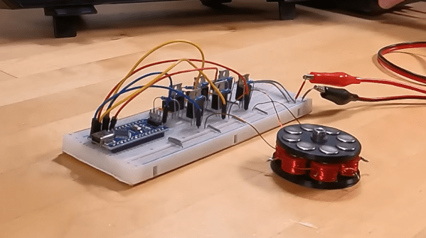
[Levi] whipped up his brushless DC motor design in OnShape. The motor has six coils in the stator, with the rotor carrying eight neodymium magnets. It’s an axial flux design, with the rotor’s magnets sitting above the coils. This makes construction very easy using 3D printed components. Axial flux motors also have benefits when it comes to power density and cooling, though optimization is outside the scope of [Levi]’s work here.

[Levi]’s video covers both the development of the motor itself as well as the drive circuit, too. The latter is of key value if you’re interested in the vagaries of driving these motors, which is far more complex than running a simple brushed motor. He even gets his motor up to 12,500 rpm with his homebrewed drive circuit.

Making your own motors can help you solve some difficult engineering challenges, like building motorized rollerblades. Alternatively, if winding coils sounds too slow and too hard, you can just use off-the-shelf gear and hack it to make it work. Here, we support both methods.

Continue reading “You Can 3D Print A 12,500 RPM Brushless Motor”

Spindle Upgrade Makes PocketNC Faster And Smoother

Conventional wisdom says that rigidity is the name of the game when it comes to machine tool performance. After all, there’s got to be a reason for CNC machines that need specialized rigging companies just to deliver them. But is there perhaps a way for the hobby machinist to cheat a little on that?

From the look of [Ryan]’s PocketNC spindle upgrade, it seems like the answer just might be yes. The PocketNC, a much-coveted five-axis CNC mill sized for the home shop, has a lot going for it, but as with most things, there are trade-offs. Chief among these is a lack of the usual huge, heavy castings used for CNC machines, which results in the tendency for the cutting tool to chatter or even stall out if you push the speeds and feeds too far. After a good intro to some of the important metrics of machining, such as “material removal rate,” the video below delves into how MRR affects chip load which in turn results in chatter.

The easy fix for chatter, of course, is to take smaller cuts. But [Ryan] decided to increase the spindle speed to take lighter cuts, but to do it really fast. The hardware for this includes a 3,500 KV high-torque brushless DC motor and a custom spindle attachment. The motor is connected to the spindle shaft using pulleys and a drive belt, and the shaft is supported with stout bearings that can be pre-loaded to fight backlash. The end result is three times the stock 10,000 RPM spindle speed, which lets [Ryan] see a 300% increase in cycle time on his PocketNC. And as a bonus, the whole thing requires no permanent modification to the machine and can be easily removed.

We think [Ryan] did a great job breaking this problem down to the essentials and hacking up a low-cost solution to the problem. Continue reading “Spindle Upgrade Makes PocketNC Faster And Smoother”

Single Flex PCB Folds Into A Four-Wheel Rover, Complete With Motors

You’ve got to hand it to [Carl Bugeja] — he comes up with some of the most interesting electromechanical designs we’ve seen. His latest project is right up there, too: a single PCB that folds up into a four-wheel motorized rover.

The key to [Carl]’s design lies with his PCB brushless motors, which he has been refining since we first spotted them back in 2018. The idea is to use traces on the PCB for the stator coils to drive a 3D printed rotor containing tiny magnets. They work surprisingly well, even if they don’t generate a huge amount of torque. [Carl]’s flexible PCB design, which incorporates metal stiffeners, is a bit like an unfolded cardboard box, with two pairs of motor coils on each of the side panels. This leaves the other surfaces available for all the electronics, with includes a PIC, a driver chip, and a Hall sensor for each motor, an IMU and proximity sensor for navigation, and an ESP32 to run the show.

With machined aluminum rotors and TPU tires mounted to the folded-up chassis, it was off to the races, albeit slowly. The lack of torque from the motors and the light weight of the rover, along with some unwanted friction due to ill-fitting joints, added up to slow progress, especially on anything other than a dead flat surface. But with some tweaking, [Carl] was able to get the buggy working well enough to call this one a win. Check out the build and testing in the video below.

Knowing [Carl], this isn’t the last we’ll see of the foldable rover. After all, he stuck with his two-wheel PCB motor design and eventually got that running pretty well. We’ll be keeping an eye out for progress on this one.

Continue reading “Single Flex PCB Folds Into A Four-Wheel Rover, Complete With Motors”

Photograph of a BLDC motor controller circuit board

Take A Ride Through The Development Of A Custom BLDC Motor Controller

The folks over at the [Barkhausen Institut] are doing research into controlling autonomous fleets of RC cars and had been using off the shelf electronic speed controllers (ESCs) to control the car motors. Unfortunately they required more reliable feedback for closed loop control of the motors, so they created their own open source hardware brushless DC (BLDC) controller.

The motor controller they developed uses an STM32 microcontroller that talks to a TMC6140 3 phase MOSFET driver to drive 6 IRLR 2905 MOSFETs. The [Barkhausen Institut] researchers went with the SimpleFOC library as the basis to program the STM32, with installed hall effect sensors indicating motor orientation for their closed loop control.

Designing a functioning BLDC and ESC controllers can be subtle, and their post goes into details about the problems and solutions they came up with to deal with with what was ultimately improper isolation of the MOSFETs interfering with the power rail for the STM32. The source for their BLDC motor controller is available through their GitLab page. For more information on the parent project that uses the BLDC driver, be sure to check out their work on a connected convoy of RC cars.

There’s now a wealth of open source BLDC drivers and projects, many of which we’ve featured in the past, like the Moteus and haptic smart knob, and it’s nice to see other projects explore different options.

Exploring The Hall Effect For Haptic Feedback PS4 Joysticks

Modern gaming console controllers aren’t without their annoyances — Joy-Con drift, anyone? The problems might stem from design deficiencies, but we suspect that user enthusiasm and the mechanical stress it can introduce might play a significant role as well. Either way, [Marius Heier] decided to take a look at what would be required to build a better joystick and came up with some interesting results.

The first video below lays the basic groundwork, with a bunch of experiments with 3-axis Hall effect sensors, specifically the Texas Instruments TMAG5273 and TMAG5170. They’re essentially the same sensor with different interfaces — SPI for the 5170 and I2C for the 5273. Using just one of these sensors, he was able to build a joystick with the usual X- and Y- axis control, but also with a rotary axis. What’s more, he built a motorized version using two NEMA 17 steppers to mechanically drive the stick back to center.

The joystick is bulky, but it looks like he’s got plans for a much smaller one with [Carl Bugeja]-style PCB motors that should fit into a PS4 controller. That’s the subject of the second video below, which uses a different Hall sensor — an Allegro A1304 — and is mainly concerned with getting the output of a non-motorized but considerably miniaturized joystick stick talking the language that the controller expects. It’s not a simple process, but it seems to be coming along nicely, and we’ll be watching progress closely.

Continue reading “Exploring The Hall Effect For Haptic Feedback PS4 Joysticks”

This Electric Outboard Conversion Makes For A Quiet Day On The Water

Nothing beats a day on the lake in a little boat with an outboard motor putt-putting along behind you. It’s great fun, if perhaps a little noisy with all that putting going on. And maybe that oily sheen on the water in your wake is not so nice. it could be that the fish are a little annoyed with your putting, too. Come to think of it, outboard motors are a bit of a problem.

Fortunately there’s a better way, like converting an old outboard motor to electric. It comes to us by way of [Anton], who happened upon the perfect donor platform — a 5-hp outboard by Crescent, sporting a glorious 1970s color scheme and a motor housing shell perfect for modding. He started by ripping the old engine and drivetrain out of the housing to make room for the BLDC motor and its driver. The motor was a project in itself; [Anton] rewound the original stator with much thicker wire and changed the coil configuration to milk as much torque as possible out of it. What started as a 180-kv motor ended up at 77 kv with much more copper and new Hall sensors for the controller. He also put a ton of effort into waterproofing the motor with epoxy resin. With a 3D-printed prop and a streamlined fairing, the new motor looks quite at home on the outboard. In fact, the whole thing barely looks customized at all — the speed control is even right on the tiller where you’d expect it.

The video below shows the build and a test run, plus an analysis of the problems encountered, chief of which is water intrusion. But as [Anton] rightly points out, that’s easily solved by reusing the original driveshaft and mounting the motor above the waterline, like this. Still, we like the look of this, and the idea of knocking around on the water nearly silently seems wonderful.

Continue reading “This Electric Outboard Conversion Makes For A Quiet Day On The Water”

An In-Depth Look At The Haptic Smart Knob

At Hackaday, we love those times when we get a chance to follow up on a project that we’ve already featured. Generally, it’s because the project has advanced in some significant way, which is always great to see. Sometimes, though, new details on the original project are available, and that’s where we find ourselves with [Scott Bez] and his haptic smart knob project.

Alert readers may recall [Scott]’s announcement of this project back in March. It made quite a splash, with favorable comments and a general “Why didn’t I think of that?” vibe. And with good reason; the build quality is excellent, and the idea is simple yet powerful. By attaching a knob to the shaft of a brushless DC motor and mounting a small circular LCD screen in the middle, [Scott] came up with an input device that could be reprogrammed on the fly. The BLDC can provide virtual detents at any interval while generating haptic feedback for button pushes, and the LCD screen can provide user feedback.

But how is such a thing built? That’s the subject of the current video, which has a ton of neat design details and build insights. The big challenge for [Scott] was supporting the LCD screen in the middle of the knob while still allowing the knob — and the motor — to rotate. Part of the solution was, sadly, a hollow-shaft motor that was out of stock soon after he released this project; hopefully a suitable replacement will be available soon. Another neat feature is the way [Scott] built tiny strain gauges into the PCB itself, which pick up the knob presses that act as an input button. We also found the way button press haptics are provided by a quick jerk of the motor shaft very clever.

This is one of those projects that seems like a solution waiting for a problem, and something that you’d build just for the coolness factor. Hats off to [Scott] for following up a sweet build with equally juicy details.

Continue reading “An In-Depth Look At The Haptic Smart Knob”