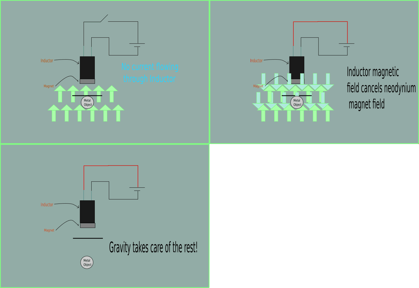
Magnets are awesome. Electromagnets are even cooler. But what if you could make a semi-permanent switchable magnet that acts like an electromagnet, but doesn’t use any energy to hold metal? You’re going to want to take a look at this Low-power Magnetic Hold and Release Mechanism.
It’s actually a very simple concept. It is basically an electromagnet attached to a permanent magnet — it’ll hold any metal object exactly as you’d expect — but if you run current through the inductor attached to it, the magnetic field created by the electricity will temporarily cancel out the field of the magnet — thus freeing your object being held. Since gravity is pretty fast acting, this impulse of current doesn’t need to be very long, only fractions of a second.
Now the real question is how big could you go? We covered another project a while ago called Open Grab which discusses the possibility of using technology like this in Quadcopters.
For a solution that uses no power at all take a look at switchable magnet clamps used for welding — they’re pretty cool — but patent protected of course.


A patent does not stop any of us from using the idea, in fact, it REQUIRES that we be given enough information to build it.
Just can’t sell it…
wouldn’t the inductor ruin the magnet after awhile?
I thougth of that too. I think it depends on the strength of the magnetic puls the coil creates. There is somewhere a level that will remagnetise the magnet.
Nope… Hard magnets won’t depolarise. But this is nothing new. Used industrially.
Yes they willl, eventually.
You can speed the process by heating the magnet or vibrating it while it’s in the opposing field.
They absolutely will demagnetize over time. They were magnetized with an electromagnetic pulse weren’t they?
Could you pulse the inductor in the opposite direction (H-bridge?) to avoid depolarization?
Probably could, to help re-magnetize it.
Cool! :)
Magnetic welding clamps just move the magnet away when you turn the switch. I can’t see anyone really enforcing that patent. But then again – patent litigation in the US is quite different to the rest of the world, so I could be wrong (I’m in the UK).
I should have started that with ‘A lot of cheaper magnetic welding clamps….’ :) The more expensive ones turn two magnets so they cancel out. But most are more of a hindrance in practice as they tend to pull the arc or attract metal filings and spatter.
All the magnetic bases I’ve seen use a single cylindrical magnet located between two steel pole pieces. Depending on the magnet’s position, the flux is either shorted by the pole pieces, resulting in little or no attraction, or it passes out through the pole pieces into the underlying metal.
I’m sure the concept was patented at one time, but everybody and their Chinese uncle is making clamps/bases like this.
I agree. I have seen these for the last 30 years from various companies. US Patents don’t last that long, even if the patent holder pays maintenance fees.
Agreed the magnet will depolarise with this over time and you need to put the paper with the key closer and closer in time (it might take years or months though). And indeed a simpler solution would be something that just moves the magnet a bit higher for a release…
thats how magnetic door end-stops is working, nothing special, nothing new.
lol good point
I remember reading an article on the switched redirection of a permanent magnetic feild by means of a relitively small pulsed electromagnetic feild.
The basic principle was to have two paths a bit like a set of scales with two bottles of water and a pipe connecting them. It only takes a little push to make it lock position one way or the other.
It was used to increase the output efficiency of an electric motor.
I gave it a go with a few different designs. I found that an araingemt of four magnets separated by small pieces of metal arranged in two pairs held together with two laminated metal blocks either side. With the magnets slightly recessed below the ends of the side blocks.
Either end was where the switching happened and the control coils were positioed in between the two groups of magnets on the side blocks.
http://newsoffice.mit.edu/2013/simple-scheme-for-self-assembling-robots-1004 this is a good read their method uses weaker magnets and an electromagnet to disable the neodymium magnet but the idea is similar
Low power relays that latch in both directions are useful in many applications requiring relay switching without power drain. They can be used for switching RF, and are often used in the bandpass filter switching of transceivers.
Implementations using reed relays, coils and permanent magnets are commercially available from companies like Meder Electronics.
They have a clear description of how they work in their Application Note AN0209-1[PDF].
A pulse in one direction closes the relay. A pulse in the opposite direction opens the relay.
If you want an exceptionally common use of this technology, look in any modern laptop optical drive. They use power-release magnet setups for the tray-release mechanism. I have dozens of the lil buggers sitting around.
huh cool *rips apart laptop
Yeah, now I’ll be tearing apart old laptop trays too.
This device would be called an electropermanent magnet.
http://en.wikipedia.org/wiki/Electropermanent_magnet
No, that’s different.
For those who want an efficient alternative and don’t want to depolarize their magnets:
https://encrypted-tbn1.gstatic.com/images?q=tbn:ANd9GcQRCc-mq7ZTew5LdT-2DtPQJh_3EgQoVqP_HpD0sxZ9LgT33kEZew
You can over saturate the metal so balance is key. Too little and it can’t attract well enough, too much and it takes too much energy to redirect the flux.