Fail Of The Week is a long-running series here at Hackaday. Over the years we’ve been treated to a succession of entertaining, edifying, and sometimes downright sad cock-ups from many corners of the technological and maker world.
You might think that we Hackaday writers merely document the Fails of others, laughing at others’ misfortunes like that annoying kid at school. But no, we’re just as prone to failure as anyone else, and it is only fair that we eat our own dog food and tell the world about our ignominious disasters when they happen.
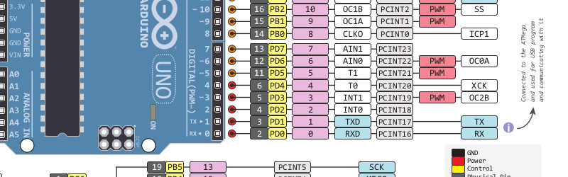
And so we come to my week. I had a test process to automate for my contract customer. A few outputs to drive some relays, a few inputs from buttons and microswitches. Reach for an Arduino Uno and a prototyping shield, divide the 14 digital I/O lines on the right into 7 outputs and 7 inputs. Route 7 to 13 into a ULN2003 to drive my relays, tie 0 to 6 high with a SIL resistor pack so I can trigger them with switches to ground. Job done, and indeed this is substantially the hardware the test rig ended up using.
So off to the Arduino IDE to write my sketch. No rocket science involved, a fairly simple set of inputs, outputs, and timers. Upload it to the Arduino, and the LED on pin 13 flashes as expected. Go for a well-deserved lunch as a successful and competent engineer who can whip up a test rig in no time.
Back at the bench refreshed by the finest British pub grub, I started up the PC, plugged the shield into the Arduino, and applied the power. My sketch worked. But wait! There’s a slight bug! Back to the IDE, change a line or two and upload the sketch.
And here comes my fail. The sketch wouldn’t upload, the IDE reported a COM port error. “Damn’ Windows 10 handling of USB serial ports”, I thought, as I’m not a habitual Windows user on my own machines. Then followed something I’ve not done for quite a while; diving into the Windows control panel to chase the problem. Because it had to be a Windows problem, right?
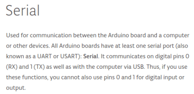 The seasoned Arduinisti among you probably spotted my fail four paragraphs ago. We all know that pins 0 and 1 on an Arduino are shared with the serial port, but who gives it a second thought? I guess I’d always had the good fortune to drive those pins from lines which didn’t enforce a logic state, and had never ended up tying them high. Hold them to a logic 1, and the Arduino can’t do its serial thing so sketches stay firmly in the IDE.
I could have popped the shield off every time I wanted to upload a new sketch, but since in the event I didn’t need all those inputs I just lifted the links tying those pins high and shifted the other inputs up the line. And went home that evening a slightly less competent engineer whose ability to whip up a test rig in no time was a bit tarnished. Ho hum, at least the revised sketch worked and the test rig did its job exactly as it should.
So that’s my Fail Of The Week. What’s yours?
Header image: pighixxx.com, CC-BY-ND via MarkusJenkins
 Fail of the Week is a Hackaday column which celebrates failure as a learning tool. Help keep the fun rolling by writing about your own failures and sending us a link to the story — or sending in links to fail write ups you find in your Internet travels.


The real fail is using external pull-ups, instead of INPUT_PULLUP, which would have allowed the serial port to work, as well as the buttons ;)
A lot of various sketches and snippets on the Internet seem to forget most of these kinds of devices have at least internal pull-up resistors, some have pull-downs, too, and then people end up tussling around with external resistors and stuff and making a mess of things.
As a matter of fact, no. I’ve had the exact problem which would follow to what you suggest.
The internal pullup/down of a microcontroller is very weak (in the range of 30k-50k). I did recently a project where I placed the buttons far away from the microcontroller. The wiring went by some other wires driving LED-strips. To test it I of course set one button set one colour in LEDs and the other button to set another colour. Oh, the disco that followed! I had built a very nice random number generator/proximity detector (when I came close to it, the disco seemed to change a bit). The internal pullups where too weak, so I solved the problem by adding external (strong, about 2k) pullups, which solved the problem really nicely. Other solutions could have been to solve it in software using some debounce function.
So that’s my fail (not this week, but not very long ago): Always use external pulls if your input is far away from your source, especially if your cables run by something with a little more high power.
True, but 2k is driving it very hard! If you need to run that long wires, maybe you should consider either shielded cable or differential signalling. 50k really isn’t all that weak for normal wire lengths.
2k is 2,5mA at 5V – that is not hard in any way for a push-button and not really hard for a CMOS output to drive. But instead to a really low pull resistor I would use a capacitor right at the input. 100nF to 1µF, depending on the necessary reaction speed of the button.
For debouncing, just do it in code. When a key is pressed, wait a few ms, then check it’s still pressed. Works 100% for me.
I abused the word hard here… Ignore that for now. My point is, you almost never need anything below 30-60k, especially not if the pull-up is right next to the microcontroller.
You only need to make the uC register it as a logic high.
2k would just be a huge waste of power IMO.
But sure, for de-bouncing, a hardware solution is the way to go (again IMO).
no no, the real fail is using Arduion
/ducks
To be fair, it doesn’t really matter what microcontroller (or language) you use. As long as you know how to program it without quirks it’s good enough ;)
Actually, arduino is really good for quick idea-testing, and you can always write the code in AVR-C if you want to and flash it to a bare chip w/o arduino bootloader.
Yes, just like the dozens of people I see each week who did something on their arduino then come whining to various avr and microcontroller channels when they can’t figure out how to use digital_write or some other arduino lib when not doing the arduino thing.
Start with bare bones avr programming please! It’s so much less painful for those of us who have to retrain you!
[:
Just my $0.02 worth.
I think it’s fun to learn and teach (though frustrating sometimes), so I disagree :)
If a person is new to microcontrollers, then I’ll use the top-down approach to keep them interested in learning. They want to see results and I totally get that!
They’ll have plenty of time to make stupid mistakes and learn along the way. I bet that most of us didn’t start out with C either (rather it was something like BASIC->ASM->C).
I would argue that assembly is easier to learn than C, but maybe that’s just me?
Just to clearify what I just wrote. I think it’s a good thing for people to start with something simple, like arduino’s, since it hides a lot of the uglyness of dealing with registers an such, which newbies don’t really need to know right off the bat.
I think it’s much better for them to use arduino, while learning machine code.
People that don’t want to put in time or effort to understand/think/read will make more avoidable mistakes that people that do. The framework can only do so much when it cannot control or protect the user from doing.
“arduino” can be used as a filter for ignoring the noobs.
I am of the generation who learned this craft with an 8-bit processor, some memory chips, a bunch of support logic, and a bunch of port, UART, and ADC chips. Then we had to sit down and hand assemble the code. If you haven’t assembled a Z80-based microcontroller on Veroboard, maybe you don’t quite understand why I picked up an Arduino without a second thought :)
Very true. I cut my microcontroller teeth thirty years ago in the 8-bit days, so pull-up resistors are a habit.
I did the opposite fail, by assuming I could just use the internal pull-ups on BeagleBone, thus, no footprint on PCB for pull-up resistors. Turns out the IO part on BeagleBone is totally messed up, with a bunch of partially working libraries and many of them do not actually support the pull-ups (and some don’t support all PWM channels etc..)
External resistors are required when you need a well defined state during reset, or before programming. That’s an easy mistake to make.
My fail this week was assuming the connectors were oriented on the PCB the same way there were oriented on schematic for the Acorn A3000, when converting it to a USB keyboard – full story here: http://blog.tynemouthsoftware.co.uk/2016/04/acorn-a3000-usb-keyboard.html
“And went home that evening a slightly less competent engineer”
I would say you went home more competent, even if it is something obvious in hindsight, making mistakes only make us better. Good engineers have just made all the mistakes already…
Hear Hear! The difference between a good engineer and a so-so one is not seen when things go well, but rather when things go wrong. Everyone makes mistakes – it is the capacity to recognize and fix them with grace that separates the good from the merely competent. You built it, you troubleshot it, and you have the confidence to share the experience with others – it’s all good.
It’s a bit of a newbie error, but if you can make those after 30 years, I suppose it shows you never stop learning!
well, I never stop making misteakes, so that’s good, right?
I haven’t bought an Arduino yet but I am reading a few books. This is exactly the kind of mistake I’m going to make; and I won’t figure it out until months later probably. So many ideas, so very little experience.
We have to crack a few chickens to make an omelet.
I love fail of the week. Makes newbies like me feel better!
Stop reading books and just jump in, I say! I bought a Nodemcu-clone (ie. ESP8266) and just kind of dove in without much preparation and I’ve learned quite a lot since — buy a Nodemcu, buy one or several different kinds of official Arduinos, maybe even one of the Mable Mini – clones and learn about the various differences and stuff in practice!
Oh, and stick your head in #arduino IRC-channel on Freenode or some similar chat-service so you can pester all the more-knowledgeable people with your ignorance — they may claim they hate you, but secretly they feel powerful when newbies shower them with attention ;)
Agree with this completely. I was a lurker…a reader….a “I’ll do that someday!” type of guy. Then when I had a few extra bucks and a bit more than my normal amount of confidence I bought my first UNO and now I have built a few dozen projects with it or variants including ESP8266.
And I suggest diving into a Pi too! No better way to learn than to do! And with a community of builders both here on Hackaday and throughout the world your problem can be solved with some simple searches.
Jump in, and good luck!
I am still very much in the learning-phase myself, having just started with this stuff a few months back! That said, I have a lot of interest in actually learning and understanding things and I am tempted to try and build my own version of Nodemcu or the el cheapo, generic STM32F103C8T6 – board. I wouldn’t be doing a custom PCB or anything like that — I was just thinking of using a generic protoboard PCB off of eBay — , and I’d use non-SMD components because they’re just too tiny for me, so it’d be several times larger than the real thing and just as much uglier, too. Still, I think it would be a nice excercise for my budding skills! I can mostly understand how to read the schematics, so turning those into an actual thing would be fabulous.
I’d just need a whole bunch more components, and if I went with the STM I’d also need one of those small heat guns that are meant for electronics work so I could get that tiny SoC soldered to a LQFP48-to-DIP adapter… Anyone happen to have an extra one just lying around, eh..? ;)
el-cheapo STM32F103C8T6 board is almost DIP already, has critical component fitted correctly (osc, USB, jtag connectors). So why bother?
Some time ago I thought that soldering any SMD IC without hot-air station is undoable. But then I soldered TQFP-100 package to adapter board using conventional soldering iron using drag soldering method and good quality flux. Since then I did some more work with SMD, and it’s quite easy, even without hot-air. The smallest parts I worked with were some 0603 resistors, which is an achievement for someone who is both near-sighted, one-eyed and suffers from glaucoma and lack of any visual aids…
mac012345: You missed entirely the “to learn stuff” – angle here.
Heat gun meaning a hot air rework tool? You don’t need that for LQFP48. Any soldering iron sufficient for normal electronics will do, even if it has a fairly broad tip. The trick is that you need a LOT of flux, but only a LITTLE solder. Apply no-clean flux to the pins and pads (excess doesn’t hurt), and then with a bit of solder on the iron tip, lightly drag it across the pins. The surface tension and wetting properties do most of the work for you. Any bridges can be removed with a bit more flux and a clean iron tip, or with solder wick if more stubborn.
“Just jump in” applies to this too. I was very nervous the first time, but succeeded with only a few bridges, all easily removed. Much easier than I expected. Since then I’ve gotten better at estimating how much solder is needed on the tip. I also cranked up the iron temperature. On that first try, I was using a conservative 550°F (for old-fashioned lead/tin solder), as I was worried about applying too much heat. After a bit of experimentation though, I found that at 600°F I could solder faster *and* with better results; so I actually end up applying less heat despite the slightly higher temp.
no he didnt, this isnt the eighties, soldering thru hole is learning to build buggy whips
plus you make it too complicated to have an argument for putting it for later
stm32 boards are $2 http://www.ebay.com/itm/STM32F103C8T6-ARM-STM32-Minimum-System-Development-Board-Module-For-Arduino-NJIU-/361532157242
rasz_pl: Yes, I know ready-made boards are cheap, but what the hell do I learn from buying a ready-made board? I actually have one already, and it still doesn’t help me learn how to build one myself! Again, you are completely missing the whole point of learning something.
I built one here: https://hackaday.io/project/6607 The only reason I did it was that I had extra space on a PCB batch and I already have the ARM chips. I would have bought the clones otherwise.
To save others the G**gle for Mac012345’s comment
http://www2.st.com/content/st_com/en/products/microcontrollers/stm32-32-bit-arm-cortex-mcus/stm32f1-series/stm32f103/stm32f103c8.html#design-scroll
How is that relevant to the discussion at hand?
remember to keep a common ground!!!!! this will save you so much grief. unless you’re doing isolated circuits or weird analog things… but that’s a whole other ballgame.
I’m a fan of common ground and opto-isolation myself.
We canall save a lot of grief if we just find common ground.
White, black, brown, yellow…
The color of your wire doesn’t matter. Inside its all copper.
+1
Just blow $1.50 delivered and buy a clone Digispark, or Arduino nano clone for $4 again delivered worldwide. The bits are so cheap now, so are breadboards, steppers, and SCR relays are pocket change, or buy a starter kit.
There’s advantages to buying a ready-made kit, complete with book and software, even if it costs more than buying the bits yourself. You know the stuff in it has been tested to work (well, if it’s any good). Helps you narrow down errors, and separate your own mistakes from ones in your setup. Having a known-good state is always invaluable in fixing problems.
Once you’ve got that down, though, yep $4 Arduinos ahoy!
Thanks for the advice and inspiration guys!
That thread tree-whatever it’s called made my day.
Bookmarked.
if im getting this right the moral of the story is “Dont put data lines needed for operation in an improper state”
Very true:) I’m lazy, that’s all.
Same applies to PICs. Be careful of what you do with MCLR, PGD, PGC, and PGM. Fortunately with the high pin count and low prices of modern PICs, it’s less of an issue with less requirement to reuse those pins as it was in the past. Still applies on low pin count varieties.
i have had issues before mainly with SPI where i used one of the lines, accidentally activated the SPI controller on those pins on all those SPI lines became unusable … i think it was a cheap ST micro tho
Another fail; in making “the course of thousand mices”, with an atmega32u4 i didn’t leave 1-2 seconds of pause on setup. So as soon the sketch is uploaded or the micro attached to usb, it will unleash so much clicks at random locations that will crash or lag the GUI. Solution? Disable mouse with that id.
And if you use a hardware programmer for faster sketch uploads via the ICSP header then you need to be careful with pins 11-13 for very much the same reason.
I remember I built a walking robot where som of the servos wwere connected to the ICSP hader. The robot was very sad while uploading a program.
haders gonna hade!
B^)
I had similar problems with the NavSpark mini. Since the mini is so small, it only has a single set of Serial lines. When I used them in a project (which required changing their default speed) I could no longer program my mini.
Fortunately in that case there was an obscure but simple fix. You tie SDA and SCK lines high and BOOT_SEL to ground to program. Perhaps it’s not so obscure to find now, but the first time I encountered it I searched a long time.
I simply don’t use those serial lines at all (except for communication), since I wasn’t sure how they are actually connected. Just leave them alone. My biggest fail? Hmmm … There were many :) I think that the biggest one was when I mixed up three phase wires (they were all black) on electrical panel, causing direct three phase 380 V short circuit. I was puzzled why main fuses keep blowing up :)
Perhaps somewhat ironically, I discovered a while ago that my Propeller-based project stopped working when I disconnected the Prop-plug (basically an FTDI controller), and that was fixed by ADDING a pull-up resistor on the receive line.
Having worked exclusively with bare MCU chips and code, I know how to allocate and configure multipurpose pins. Yet give me an Arduino Uno, and I’d probably make the same mistake, for a different reason.
I would assume that for a board/environment intended to abstract away technical details (like which actual MCU pin I’m using), that the designers would not expose pins already used for an essential function on a GPIO header. Exposing them as the *first two* GPIO is particularly counter-intuitive. Making them the *last two* would make more sense.
I am not a seasoned Arduinisti and have learned from your fail. I learn quite a bit from my mistakes. Now I’ve learned from yours.
Been there! Don’t use pins 0 and 1 to read a keypad, while sending debug output about those keys to the serial console! And that’s probably what gave the infra-red library completely unreliable inputs too. Doh!
If I made Arduinos I’d put a warning on the PCB about those pins. And maybe even an option in the IDE to warn you when you’re using them, and the serial console, in the same code. Of course once it’s bitten you, you don’t need the warning again.