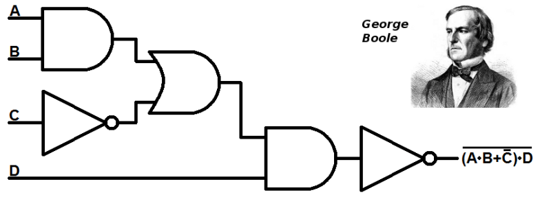
Logic gates are the bricks and mortar of digital electronics, implementing a logical operation on one or more binary inputs to produce a single output. These operations are what make all computations possible in every device you own, whether it is your cell phone, computer, gaming console etc. There are myriad ways of implementing logic gates; mechanically, electronically, virtually (think Minecraft), etc. Let’s take a look at what it takes to create some fun, out-of-the-ordinary gate implementations.
How they work
As an example, let’s consider the AND gate (the others are OR, NOT, NAND, NOR, XOR and  XNOR). Electronic gates operate on two nominal voltages, normally 0 V and 5 V, representing the logic 0 and the logic 1, respectively.
The AND gate has two inputs A and B. The output of the gate, A.B, depends on the two inputs according to the truth table at the right. The AND gate has a “1” output only when both A and B are 1. As you can guess, the OR gate has a 1 output when A or B are 1, and 0 only when both A and B are 0.
Every gate has its own truth table. Although these seven gates are normally considered the “basic” gates, there are some gates, such as the NAND gate, that are universal, meaning that they can be interconnected to construct all other gates.
Combining Gates
 Logic gates can be combined to perform any computation. There are millions of them in a computer chip. But let’s see a very simple application of the AND gate.
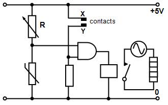
At the left is a schematic for an automatic thermostat. The heater must turn on if the water is cold, but only if there is enough water in the tank. Contacts X and Y are near the top of the tank and if they are covered with water a signal is sent to one of the gate’s inputs. The thermistor senses the water temperature, and if it is cold enough, a signal is sent to the other gate input. Therefore the heater goes on when there is sufficient water and the temperature is cold enough.
Other Gate Implementations
Contemporary logic circuits use MOSFETs as the elements to build gates, but there are many ways to implement them. Using relays is one of them, and you can literally see how they work. [Andrew Kingsolver] has done an excellent job of explaining relay-based logic. The image below show his implementation of the AND and OR gates. A quick analysis of the circuits reveals how the truth tables are obtained from the inputs, represented by the two switches (energizing the coil in the relay will push the contacts to the far poles).


In order to understand how arithmetic can be done with logic gates, the half adder is a good example. [Andrew Kingsolver] has done that as well. It takes two inputs (0 or 1) and outputs a sum and a carry, in binary of course. This can be implemented with an AND gate and an XOR gate. As you may know, early computers were relay-based, and you can even build one just for fun, if you have the time.
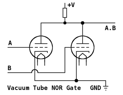
Vacuum tubes replaced relays as the main elements for computation. A simplified circuit that implements the NOR logic gate, which only outputs 1 when both inputs are o, is show at the right. The tube grids are the inputs. There is no output when both grids are low, since the current flows to ground. When voltage is applied to both grids, the tubes become basically an infinite resistance, and a current flows to the output.
As with relays, all kinds of logic circuits were made using vacuum tubes. There were 17,468 of them in the ENIAC computer. Tube circuits were bulkier and power-hungry compared to relays, but the speed of computation was much larger.


Eventually, silicon arrived, and vacuum tube logic was replaced with diode and transistor logic. This represented a dramatic increase in speed and a great reduction in size and power consumption. You guessed it, diodes can also be used to build logic gates, but not all of them, only the AND and OR gates can be built using diodes only. However, by adding a transistor as an active element, all other gates can be implemented.
 The three input, diode-only AND gate is shown in the picture above. When all inputs are positive, a current will flow through the resistor and pull the output positive. If any of the three inputs is at 0 volts, current flowing through the corresponding diode will pull the output voltage down to 0 volts. The other diodes would be reverse biased and conduct no current.
How about mechanical logic gates? Sure, you can use LEGO to build gates and a half adder, or a small adding machine using wood and marbles. Of course, pneumatic logic gates can also be designed (useful in places with high levels of moisture or dust).
Some bizarre ways of building logic gates also exist. Conway’s Game of Life, perhaps the most well known cellular automaton, has been shown to be a Universal Turing Machine, meaning that anything that can be computed algorithmically can be done within the game. The game is fascinating by itself, and detailed ways of building gates in it have been described.
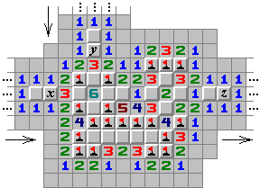
Another similar example comes from the Minesweeper game, popular in early versions of Windows. This game seems innocent, but is in fact an NP-complete problem (the hardest problems to solve).
So if you have some spare time, consider building some logic gates, after all, there are many ways to do it!


How about some pulley logic?
https://www.youtube.com/watch?v=CNbScb8v-MI
Scientific American published something similar in 1988. Dewdney published “An Ancient Rope-and-Pulley Computer is Unearthed in the Jungle of Apraphul” in Computer Recreations, April 1988. It’s re-printed in “Humour the Computer”, 1995. p117. (https://books.google.com/books?id=0Rb5jBg6sJwC&pg=PA117)
I raise you some crab based logic gates.
https://www.youtube.com/watch?v=KlRoZ0zTXvw
https://arxiv.org/abs/1204.1749
I half expected electrodes in the crabs’ nervous systems as input and sensors on the legs as output. I am both relieved and sort of disappointed. I expect much crazier things from Japan.
https://upload.wikimedia.org/wikipedia/commons/thumb/1/19/Bill_Gates_June_2015.jpg/170px-Bill_Gates_June_2015.jpg
The one kind of “Gates” Boole didn’t envision. :-)
And here’s a NOT GATES…
https://cdn.arstechnica.net/wp-content/uploads/2013/02/linus-eff-you-640×363.png
You guys are terrible. Please don’t quit your day JOBS
http://www.slate.com/content/dam/slate/articles/life/spectator/2011/10/111007_SPEC_steveJobs1977.jpg.CROP.rectangle3-large.jpg
OMG This is just cancer, Why are you doing this.
Pun threads are the nature of the Internet.
Hackaday now posts clickbaits… I want to see the minesweeper logic gate but all I have is an article with no minesweeper xDDD
I can see it, here’s a link to the image -> https://hackaday.com/wp-content/uploads/2016/12/orms.png
yeah I saw it. But I miss some explanation.
I believe this is the page that was being referenced to http://www.formauri.es/personal/pgimeno/compurec/Minesweeper.php
http://www.formauri.es/personal/pgimeno/compurec/Minesweeper.php
thank you!
Thanks.
Don’t forget hydraulic logic gates, or those built with neon lamps, both of which have real-world implementations.
Biological gates?
Sure – synthetic biological circuits are where biological parts inside a cell are designed to perform logical functions, but to the best of my knowledge there are no commercial products using these.
Wetware is too slow, thought the bioneural gel packs on voyager were stupid. Now DNA and biochemical logic might go somewhere.
The general idea is to provide an interface between biological and nonbiological logic for control of things like complex chemical synthesis or to monitor what processes are occurring in a living system. From what I gather, little hard computing is envisioned for synthetic biological circuits.
Check out this neural network implemented with reactions between DNA strands: http://www.nature.com/nature/journal/v475/n7356/full/nature10262.html
or this 4-bit square root calculator by the same folks using the same technique: http://science.sciencemag.org/content/332/6034/1196
There’s lots you can do with wetware within cells too where anything else might have problems interfacing with the biological side, e.g. this micro-RNA based cell classifier http://science.sciencemag.org/content/333/6047/1307.full or these neat oscillating bacteria that synchronize across small (within a colony) and large (across colonies) scales http://biodynamics.ucsd.edu/pubs/articles/Prindle12.pdf (https://www.youtube.com/watch?v=pOJ4AS7TXy0)
Largely because they’re near-impossible to build, except in science fiction. Reality check: Biology is hard.
https://xkcd.com/1605/
Just a nitpick… in most modern systems, 0V = Logic 1 and 5V = Logic 0. This is due to some assymetry around current sinks and sources in modern IC materials (improves fanout), and also due to the popularity of designing as much as possible around NOT and XOR gates, which get slightly simpler to implement with a HIGH being logic 0
Yeah, um, no.
In TTL (transistor-transistor logic) days, when logic levels really were 5V and 0V, signals were very often inverted logic, for a number of reasons. An open TTL circuit floats high, so if an input is unconnected, it registered as high – however, it’s a horrible idea to rely on this. A TTL driver connected to a TTL input consumes current when driving low, but not when driving high. There was also more noise margin from the transition point to ‘high’ than from the transition point to ‘low’.
However, with CMOS circuits (virtually *any* modern system) basically all of those concerns are gone. The only real reason for active low CMOS circuits now is to allow for wire-oring using open-collector interfaces, and if you search for “CMOS gate examples,” they’re all positive logic.
Note that other logic families have different logic levels too, but CMOS is by far the dominant logic family at this point.
5v=high=1 no matter what (for 5v systems). You are thinking of active low controls, such as enable lines and chip selects, which at one point mattered for fanout but no longer does.
In general that is true for anything modern. There are some old system that use active low for logic: 0v for 1 and 5v for 0. Check out the 74181 ALU, it supports both modes.
You can even switch freely between active low and active high: There is an old computer, I don’t remember its name, but uses only NOR gates. Each stage alternated between active high and active low, so that a NOR gate that connected between two stages could be replaces by a regular OR gate. It doesn’t completely get past the need for inverters (you can’t implement a computer with only OR gates), but it did simplify things quite a bit.
When I was coming up, we were drilled to use the terms “asserted” and “not asserted” and carefully avoid using “high” and “low” in order to describe when a logic signal was at a voltage that denoted True (or False) .. precisely to counter any erroneous connection between voltage and Boolean value (i.e. in some contexts, a low voltage really did denote True)
Here it is, the result of posting an article on logic design. The only totally valid response is from [pez], which you all should try and understand. There IS no validity to a statement such as, “5V = high = logic 1”.
Quick example, folks: the AND gate shown in the article is really AN OR GATE! Don’t believe me? Go look at it again, and play this simple game–if input A is low OR input B is low, THEN THE OUTPUT IS LOW.
Until you become comfortable abandoning the “3.3V = 1” mentality, you will be seriously hobbled in your attempts at logic design.
Oh, and one more tip: programming a microprocessor does not make you a logic designer, no matter how elegant the program.
To HackADay’s editors: here’s a subject which you should pursue. I’m sure that a lot of your readers would appreciate a clear, concise tutorial on this subject.
Jawnhenry? You MUST be from philly. That’s probably why you get it!
Not really, but close roots.
I developed somewhat an emotional attachment when I found that WC Fields made (at least) two remarks which I think are humorous:
…when asked his opinion of that City of Brotherly Love, his reply was, “…one night I spent a week there…”;
and supposedly is written on his tombstone, or he’s said to have wanted written
“All things considered, I’d rather be in Philadelphia.”
Thanks, pez.
If you stick inverters on the inputs and output of an OR gate, it becomes an AND gate. I haven’t got a bit of paper to hand, but if you consider 0 1, and 1 0, pretty sure the one is the other.
As far as voltage = 1, it can be. It depends, if you’re being purely mathematical it’s TRUE and FALSE, if you’re wiring up a circuit it’s voltages. Computer programming does involve a lot of designing logic. There’s no use in fencing off a particular bit of territory and calling it “logic”. The principles are simple and can apply to all sorts of things, with a lot of uses.
From someone who actively does large-system logic design, and who actively programs, and who effortlessly finds no need to mingle the two–have it your way.
Oh, and by the by: it has never been my experience that a course in logic design is a prerequisite to any course in programming, at any university or institution of higher learning. Having taught logic design for many years, I think I am qualified to state that knowledge of a programming language is of absolutely no use in learning logic design,
Have it your way…
One type of gate, which a lot research was done. Was light logic gates.
The though was the speed of light would make processors really fast.
That was years ago. So how do you like your 186,000 mps (miles-per-second)
processor today. Biggest fail I can remember to date.
That entirely depends on the switching speed of the logic circuits. Electron propagation is already pretty fast. https://blogs.mentor.com/hyperblog/blog/tag/velocity-of-propagation/
*Electric field* propagation. The electrons themselves are pokey little things, drifting around at less than 1 millimeter/second!
How long would it take for a photon of light to travel 50 mm (under 2″) across the processor die?
S.O.L. 300,000,000 meters per second.
That is why it’s such a fail. Boat loads of money and nothing to show for it.
A SOL processor would have given a Quantum processor a run for the money.
Let’s use PCB transmission lines at first, because moving signals around a die is a lot different. That and I dare you to find any modern die that’s 50 mm across. That’s gigantic.
Speed of light transmission across 50 mm, assuming vacuum:166 ps.
Electrical signal propagation across 50 mm, assuming microstrip on a 10-mil thick dielectric with constant of 4.5: 276 ps.
It’s not even a factor of two.
Yea, 50mm is a bit big. It was just an statement of the die size required back then. For processors of the time. To make a crystal substrate processor. Moore’s law was broken long ago, even today’s processors are many factors more dense than the SOL processor. Electron flow thur a medium slows down. Very measurable. The hope was SOL processor would not suffer the same effect. The downfall in SOL proc, was crystals could not be made pure enough not to scatter the light. Unless there is a big breakthrough today’s crystals still don’t cut it.
The closest thing we got going, is super conductor’s. Get it working closer to room temp, we’ll have something good.
“Let’s use PCB transmission lines at first”
That’s interesting. I’m picturing a glass PCB layer with special SMT optics for data buses.
http://motherboard.vice.com/en_au/read/quantum-leap-researchers-send-information-using-a-single-particle-of-light
Problem’s being worked on.
The big issue’s that nonlinear optics make for really shitty transistors, in just about every possible way except speed.
Let’s crowdsource computing—that is, get a large number of people, each acting as some sort of logic gate, to perform computations. With lots of blinky-blinky controlled by the human computer, it could be a great Olympics opening ceremony.
Related, it seems to me that a Game of Life played with lots of people would be pretty cool, but even omnipotent YouTube doesn’t seem to have any examples.
In Liu Cixin’s “The Three-Body Problem”, this was exactly how the alien race created their first computers. Before they had developed the manufacturing technology to build reliable mechanical or electronic computers, their army assembled into a “computer formation” and performed astronimic calculations. Each soldier was ordered to perform a simple logical computation in their mind, and to visually communicate input and output to other particular soldiers. The cavalry bussed larger chunks of data around the formation, and “faulty” gates were esecuted for failing to follow orders.
That was my favorite part of the book. It was really good. My only complaint was “Why did they bother implementing an OS to run a single program? All they need is a bootloader… :-)”
Only complaint? The idea of “before reliable mechanical computers” is silly because a slide rule is just a bunch of sticks with notches on them. They couldn’t manufacture a piece of paper with a regular grid on it? Or a compass, a straight edge…?
During WW2, General Nenonen of the Finnish Defence Forces developed the algorithms for directing fire from a multitude of guns to lob the Russians with 9 tons of shells per hectare per minute. The computers they used to compute the trajectories were made out of two translucent pieces of plastic with lines scribbled on them.
“The idea of “before reliable mechanical computers” is silly because a slide rule is just a bunch of sticks with notches on them. They couldn’t manufacture a piece of paper with a regular grid on it? Or a compass, a straight edge…?”
And Japan would have gotten so much farther if they’d figured out how to make glass, but it happened that nobody came up with the idea for thousands of years, long after they’d advanced in so many other ways.
” but it happened that nobody came up with the idea for thousands of years”
So somehow nobody got the idea of cutting notches on a stick or equivalent media – not even an abacus by dropping pebbles in little grooves on the ground – yet they developed mathematics?
That sounds like something Douglas Adams would write.
What happens when your ALU gets mangled by a trébuchet?
https://m.youtube.com/watch?v=rA5qnZUXcqo
𝘏𝘶𝘮𝘢𝘯 Brain
https://m.youtube.com/watch?v=rA5qnZUXcqo
Vacuum tube NOR gate description is wrong. It should be: when grid voltage is much lower than the GND potential (tube is in cutoff) output will be high (no anode current is flowing). If either tube’s grid voltage is higher (close to GND potential or above), current will flow through that tube and cause the output to go low (because of the anode resistor).
How about falling domino logic?
https://en.wikipedia.org/wiki/Domino_computer
Years ago a friend of mine worked at a building control company. They were looking into pneumatic logic. The reason was that the local unions made it so difficult to do installations. He would go into to a place for an installation. The union guy from the customer would have to do the actual installation while he instructed them. They would be down to the last wire and the guy would say it is quitting time. He would have to stay an extra day just so the other guy could connect the last wire.
They did some research and didn’t find any unions that claimed responsibility for stringing small air tubing. He didn’t stay there long so I never heard what happened to the idea.
Hmm, commutation isn’t mentioned.
A lot of chips are based on nothing but NAND gates as they can simulate all the others (NOR can do the same).
If you connect the inputs together then you have an inverter.
If you invert the (already inverted) output then you have an AND gate.
If you invert the inputs then you have an OR gate
If you invert the inputs and (already inverted) output then you have a NOR gate.
That’s a lot of words to state De Morgan’s theorems:
(~A)+(~B) = ~(A*B)
(~A)*(~B) = ~(A+B)
see wikipedia for more
Has anybody seriously completed or done work on MEMS based physical gates? They would probably be far slower than silicon but could be something akin to or actually diamonoid logic based and would also have their own sets of advantages. Would sort of be able to marry the world of software into the physical world, to a degree, depending on how the logic was implemented.
There is a srructure called a Quake valve, and there has been considerable theoretical work done on routing liquids with the small number of control signals.
I’d like to point out that the liquids DO NOT represent logical signals. This type of work is being developed for microfluidic lab-on-chip devices, largely for preforming chemical and biological tests.
But the open/closed values of the valves DO represent logical signals (if flow control is proportional, that’s a different matter). Ultimately, how much you can pack on a microfluidic chip is dictated by minimizing the number of possible routes you can define with a limited number of actuation signals.
FIgure 1 in the following example looks pretty logic chip inspired to me …
http://www.rsc.org/binaries/loc/2008/pdfs/papers/230_0199.pdf
We can already do that with traditional CMOS logic and regular mems devices, at far less cost, complexity and power consumption, and at order of magnitude greater speed than could ever be achieved. The only market I know of for “physical” logic is in microfluidic controls which fill niche roles where electronics are too hazardous due tot he chance of a spark (though even there it’s being superseded by newer and more reliable electronics). All of that is now transitioning to microfluidic chemistry sets for a “lab on a chip.”
http://richfiles.solarbotics.net/calc/CogitoPCB.jpg
My Smith Corona Marchant Cogito 240SR calculator uses resistor-diode and transistor-diode logic. It dates to around 1965.
So does the dust it seems.
That dust contains the DNA of some very intelligent people and in 1000 years from now they will be resurrected using it so that they can sit in the museum next to the device and demonstrate how it works to baby cyborgs.
One thing this article doesn’t mention is how you determine what logic is required to get a pre-determined output. Karnaugh maps, K-maps are the way: https://en.wikipedia.org/wiki/Karnaugh_map
Karnaugh maps are *a* way to minimize logic .. I seem to recall that they are hard to use when you have more than two terms per output term (although some quick googling turns up some links that show how to do 5 and 6 term problems). I think that large scale optimization is generally handled using specialized statisfiability solvers, but I am not an expert in digital design.
I find it quite bewildering the amount of junk thats actually useful to make machines from. its all so makeshift, and all improvised, I need my computer programming back.
I think humanity has forgotten about Japanese parametron electronics.